/EIF CONNECTING TO A 4-WIRE
’ ELECTRICAL SYSTEM: This aooliance is manufactured with ground connected ii cabinet. The ground must be revised so the green grounding wire of the
When a
The MINIMUM conductor sizes for the copper 4- wire power cord are:
40 ampere circuit 2,
1,
EJn The wiring diagram is also located on the back of the range.
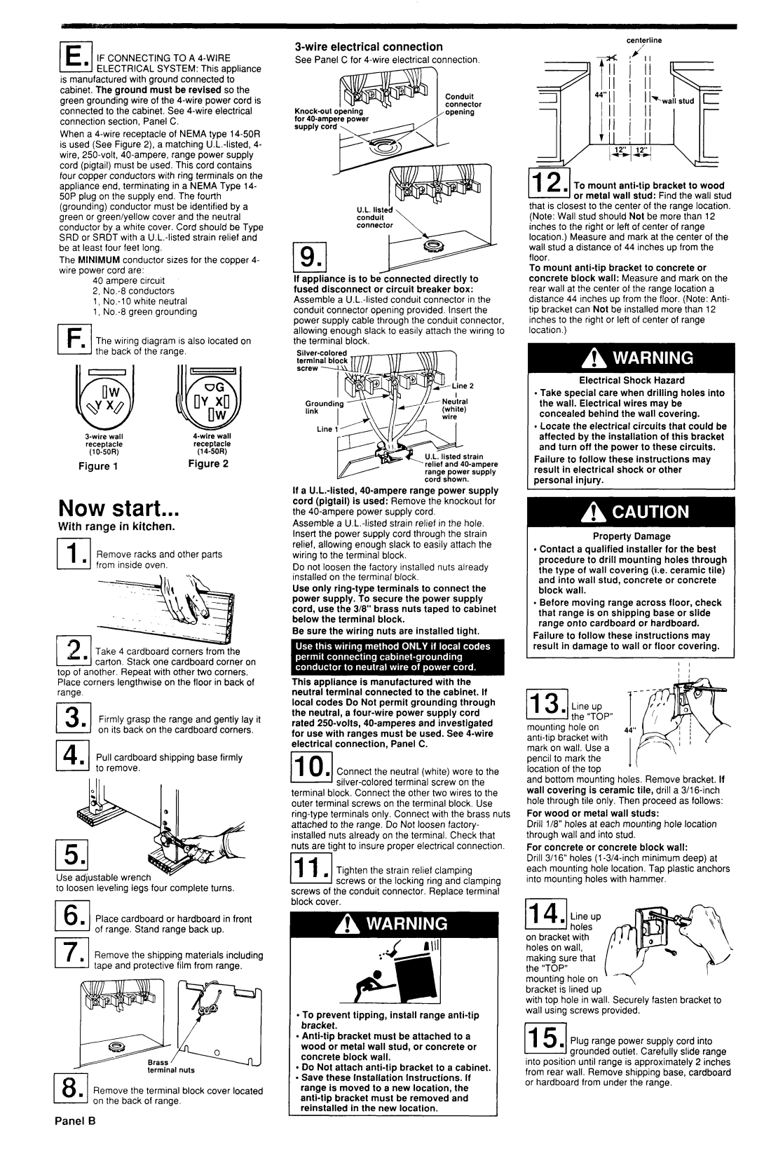
3-wire electrical connection
See Panel C for
| Conduit |
connector | |
opening | |
for 40.amDere Dower | % |
U.L. listed conduit connector \
If appliance is to be connected directly to fused disconnect or circuit breaker b&x: Assemble a
centerline
7I
,=‘c
(12(. To mount
that is closest to the center of the range location. (Note: Wall stud should Not be more than 12 inches to the right or left of center of range location.) Measure and mark at the center of the wail stud a distance of 44 inches up from the floor.
To mount
wall | wall | ||
receplacle | receptacle | ||
(14~50R) | |||
Figure | 1 | Figure | 2 |
Now start...
With range in kitchen.
Remove racks and other parts from inside oven.
Take 4 cardboard corners from the carton. Stack one cardboard corner on
top of another. Repeat with other two corners. Place corners lengthwise on the floor in back of range.
141. Pull cardboard shipping base firmly to remove.
Use adiustable wrench
to loo& leveling legs four complete turns.
El, Place cardboard or hardboard in front of range. Stand range back up.
17I Remove the shipping materials including tape and protective film from range.
,I, fermlnal nuts
181. Remove the terminal block cover located on the back of range.
If a
Assemble a
Do not loosen the factory installed nuts already installed on the terminal block.
Use only
Be sure the wiring nuts are installed tight.
This appliance is manufactured with the neutral terminal connected to the cabinet. If local codes Do Not permit grounding through the neutral, a
, Connect the neutral (white) wore to the
BEI
,Tighten the strain relief clamping
ml screws or the locking ring and clamping screws of the conduit connector. Replace terminal block cover.
l To prevent tipping, install range
l
l Do Not attach
range is moved to a new location, the
Electrical Shock Hazard
l Take special care when drilling holes into the wall. Electrical wires may be concealed behind the wall covering.
l Locate the electrical circuits that could be affected by the installation of this bracket and turn off the power to these circuits.
Failure to follow these instructions may result in electrical shock or other personal injury.
Property Damage
l Contact a qualified installer for the best procedure to drill mounting holes through the type of wall covering (i.e. ceramic tile) and into wall stud, concrete or concrete block wall.
l Before moving range across floor, check that range is on shipping base or slide range onto cardboard or hardboard.
Failure to follow these instructions may result in damage to wall or floor covering.
|
|
|
| 1 | I |
|
|
|
| I | 1 |
| . Line | up | 1 |
|
|
1131the “TOP” | ‘, | i | |||
mounting | hole | on | 4b” |
|
|
with | ‘I)ri | ||||
mark on wall. Use a |
|
|
| ||
pencil to mark | the | IF |
|
| |
location | of the | top |
|
| |
|
|
| |||
and bottom mounting holes. Remove bracket. if wail covering is ceramic tile, drill a 3/l
For wood or metal wail studs:
Drill l/8” holes at each mounting hole location through wall and into stud.
For concrete or concrete block wall:
Drill 3/l 6” holes (l
on bracket with holes on wall, making sure that
the “TOP”, mounting hole on ’
bracket is lined up
with top hole in wall. Securely fasten bracket to wall using screws provided.
Plug range power supply cord into arounded outlet. Carefully slide ranae
into position until range is approximately 2 incGes from rear wall. Remove shipping base, cardboard or hardboard from under the range.