Push cable, located on rear of
range, up and into the two hooks on the
reposition cable to insure that cable fits securely in both
/17/. If installing the range in a mobile home, you MUST secure the range to
the floor. Any method of securing the range is adequate as long as it conforms to the standards listed in the Mobile Home Installation Instructions, Panel A.
Place rack in oven. Place level on rack, first side to side; then front to
back. If range is not level, adjust the leveling legs up or down until the range is level.
Note: Oven must be level for satisfactory baking | |
conditions. | OFF |
| |
LO n | HI |
each surface unit control knob to “HI” position. Check the operation of the
cooktop elements and indicator lights.
120“88:88” should appear in the clock
n
disolav. Press the “Clock Set” button. “TIME, HR
Press the number buttons for the correct time of day. Press “Start/Enter” button to start the clock.
Check the operation of the oven element. Press the “BAKE” button.
“350”” will appear in the temperature display. The ON, Bake Element, Outer Broil Element and Oven Cavity symbols will light up in the display. Press the “Start/Enter” button.
The bottom element should glow red and the indicator light should be on. The upper element should become hot but not glow red. The oven indicator light goes off when the oven is preheated.
Press “Cancel/OFF” button.
122. Check the operation of the broil element. Press the “BROIL” button.
“500”” will appear in the temperature display. The ON, Inner and Outer Broil Elements and Oven Cavity symbols will light up in the display. Press the “Start/Enter” button.
The top element should glow red and the indicator light should be on.
Press the “Cancel/OFF” button.
To get the most efficient use from your new electric range, read your KitchenAid Use and Care Guide. Keep Installation Instructions and Guide close to the electric range for easy reference.
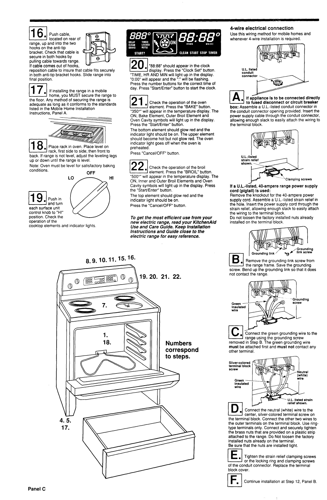
4-wire electrical connection
Use this wiring method for mobile homes and whenever 4.wire installation is required.
U.L. llsted conduit connecxor
If appliance is to be connected directly to fused disconnect or circuit breaker box: Assemble a
the conduit connector opening provided.
I
If a
Remove the knockout for the 40.ampere power supply cord. Assemble a
Do not loosen the factory installed nuts already installed on the terminal block.
8.9. IO. 11.15. ‘6. | Remove the | screw | from | |
| the | range frame. Save the grounding | ||
screw. Bend | up rhe grounding link | so that | it does | |
not | contact the range. |
|
| |
ding
Green -
Insulated wire
18. | IW | Numbers |
|
| correspond |
|
| to steps. |
lk.l.
removed in Step B. The green grounding wire must be attached first and must not contact any other terminal.
Green - Insulated wlre
- U.L. llsted strain relief shown.
PI. Connect the neutral (white) wire to the center,
the terminal block. Connect the other two wires to the outer terminals on the terminal block. Use ring- type terminals only. Connect and securely tighten the brass nuts that are provided on a plastic strip attached to the range. Do Not loosen the
Be sure that the nuts are installed tight.
(El. Tighten the strain relief clamping screws or the locking ring and clamping screws
of the conduit connector. Replace the terminal block cover.
Continue installation at Step 12, Panel B.