Cabinet-face Mounting
A![]() C
C
B ![]()
D
A. Mounting clip | C. Retaining bracket |
B. Cabinet | D. Mounting screw |
8. | Grasp sides of the compactor drawer and place the bottom |
| of the drawer into the tracks. |
9. | Lift at the handle so the drawer will go over the drawer stops. |
10. | Close the drawer. |
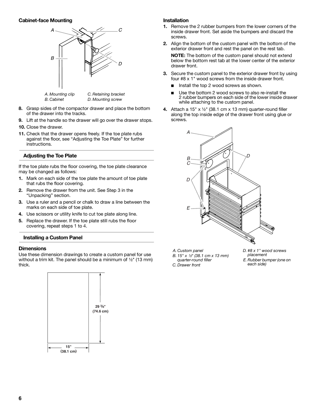
Installation
1.Remove the 2 rubber bumpers from the lower corners of the inside drawer front. Set aside the bumpers and discard the screws.
2.Align the bottom of the custom panel with the bottom of the exterior drawer front and rest the panel on the rest tab.
NOTE: The bottom of the custom panel should not extend below the bottom rest tab at the lower center of the exterior drawer front.
3.Secure the custom panel to the exterior drawer front by using four #8 x 1" wood screws from the inside drawer front.
■Install the top 2 wood screws as shown.
■Use the bottom 2 wood screws to also
2 rubber bumpers on each side of the lower inside drawer while attaching to the custom panel.
4.Attach a 15" x ¹⁄₂" (38.1 cm x 13 mm)
11. Check that the drawer opens freely. If the toe plate rubs |
against the floor, see “Adjusting the Toe Plate” for further |
instructions. |
Adjusting the Toe Plate
A
B ![]()
![]()
![]()
![]() D
D
If the toe plate rubs the floor covering, the toe plate clearance may be changed as follows:
1.Mark on each side of the toe plate the amount of toe plate that rubs the floor covering.
2.Remove the drawer from the unit. See Step 3 in the “Unpacking” section.
3.Use a ruler and a pencil or chalk to draw a line between the marks on each side of toe plate.
4.Use scissors or utility knife to cut toe plate along line.
5.Replace the drawer. If the toe plate still rubs the floor covering, repeat steps 1 to 4.
Installing a Custom Panel
Dimensions
Use these dimension drawings to create a custom panel for use without a trim kit. The panel should be a minimum of ¹⁄₂" (13 mm) thick.
C ![]()
![]()
![]()
![]()
D
E ![]()
![]()
![]()
![]()
A. Custom panel | D. #8 x 1" wood screws |
B. 15" x ¹⁄₂" (38.1 cm x 13 mm) | placement |
E. Rubber bumper (one on | |
C. Drawer front | each side) |
29 ³⁄₈"
(74.6 cm)
![]() 15"
15" ![]() (38.1 cm)
(38.1 cm)
6