Connecting the TP-305A UXGA-Audio-RS-232 Line Receiver/DA
STP Cable
Range up to 300ft (100m)
| |
123- |
|
TP |
|
Transmitter |
|
Line |
|
Data | / |
TP-305A
L |
|
INE | IN |
UXGA | OUT |
|
1
2 | L |
INE | |
| O |
| 3UTPUTS |
4
5
| A |
A | UDIO |
NALOG | |
OUT S/PDIF
RS- |
|
| |
G | 232 | 12V |
|
Tx | DC | ||
|
|
| |
XGA | Audio | / |
|
|
| XGA | |
IN | GND RXD |
| |
L |
|
| |
INE | OUT |
|
|
|
|
| |
| RS- |
|
|
| 232 |
|
|
| A |
|
|
| UDIO |
|
|
| IN |
|
|
STP Cable
Range up to 300ft (100m)
STP Cable
Range up to 300ft (100m)
124- |
TP |
Receiver |
Line |
 Audio
Audio
12V | DC |
|
XGA | OUT |
|
124- |
TP |
GND |
Receiver |
| ||
|
|
| |
Line |
|
|
|
Data | / |
|
|
| Audio | / |
|
|
|
| XGA |
XGA | OUT |
|
LINE IN
|
|
| Data | / |
|
|
|
|
|
| Audio | / |
|
|
|
|
|
| XGA | |
GND TXD |
|
|
|
|
| |
|
|
|
|
|
| |
| A |
|
|
|
|
|
RS- | NALOG | S/PDIF |
|
|
|
|
|
|
|
|
| ||
232 |
|
|
|
|
| |
| A |
|
|
|
|
|
| UDIO | OUT |
|
|
|
|
|
|
|
|
|
| |
|
| 12V | DC |
|
|
|
|
|
|
|
|
|
VGA | 232 |
| RS- |
L | TXD |
INE | A |
IN | |
| NALOG |
| RS- |
| 232 |
| A |
| UDIO |
|
Audio
S/PDIF |
|
OUT |
|
12V | DC |
|
|
|
| VGA | RS- |
|
|
|
| |
VGA | Audio |
| 232 | |
| Audio |
Computer Graphics / |
| Plasma | Plasma |
| |
Audio / |
| ||||
Plasma | Display | ||||
Display | |||||
|
| ||||
| Display |
|
|
|
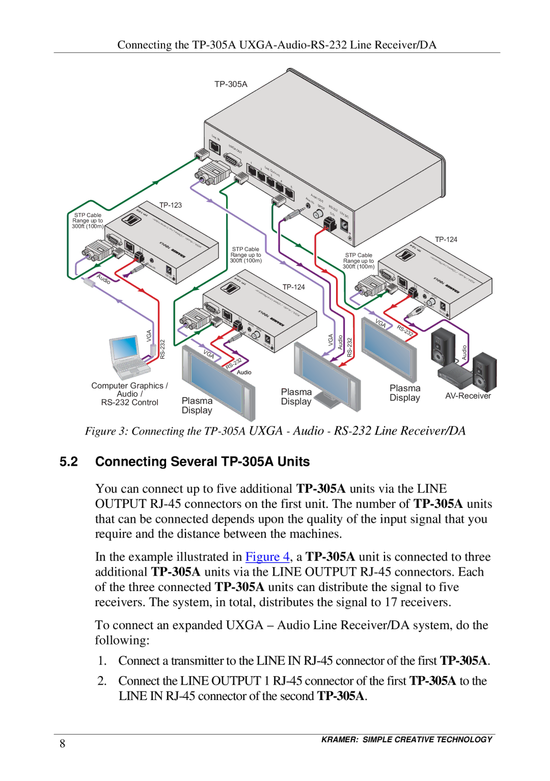
Figure 3: Connecting the TP-305A UXGA - Audio - RS-232 Line Receiver/DA
5.2Connecting Several TP-305A Units
You can connect up to five additional
In the example illustrated in Figure 4, a
To connect an expanded UXGA – Audio Line Receiver/DA system, do the following:
1.Connect a transmitter to the LINE IN
2.Connect the LINE OUTPUT 1
8 | KRAMER: SIMPLE CREATIVE TECHNOLOGY |
|