Connecting the TP-305A UXGA-Audio-RS-232 Line Receiver/DA
3.Connect the LINE OUTPUT 2 RJ-45 connector of the first TP-305Ato the LINE IN RJ-45 connector of the third TP-305A.
4.Connect the LINE OUTPUT 3 RJ-45 connector of the first TP-305Ato the LINE IN RJ-45 connector of the fourth TP-305A.
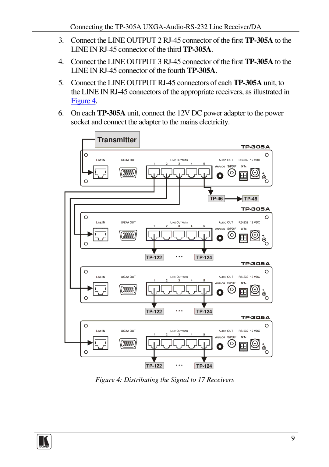
5.Connect the LINE OUTPUT RJ-45 connectors of each TP-305Aunit, to the LINE IN RJ-45 connectors of the appropriate receivers, as illustrated in Figure 4.
6.On each TP-305Aunit, connect the 12V DC power adapter to the power socket and connect the adapter to the mains electricity.
 Transmitter
TP-46 
 TP-46
TP-46
TP-305A
Figure 4: Distributing the Signal to 17 Receivers
9