Your Audio/Video Line Transmitter and Line Receiver
4Your Audio/Video Line Transmitter and Line Receiver
This section describes the:
•
•
4.1Your TP-9 Audio/Video Line Transmitter
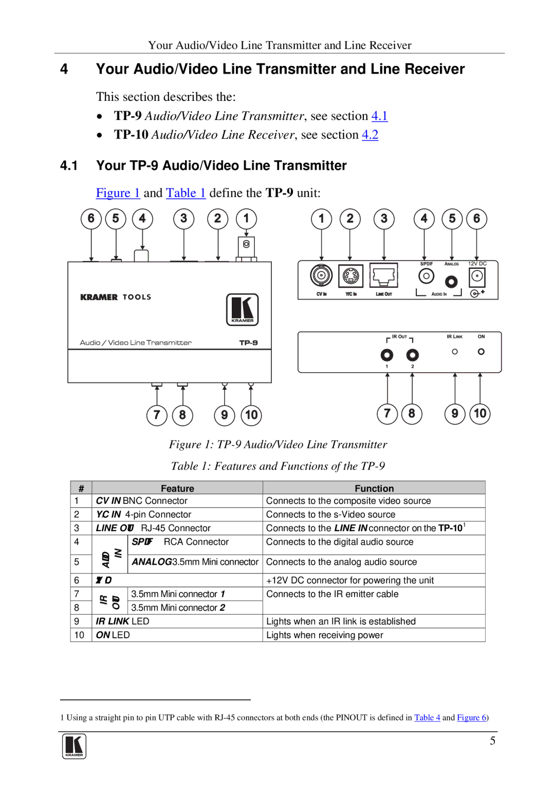
Figure 1 and Table 1 define the TP-9 unit:
6 | 5 | 4 | 3 | 2 | 1 | 1 | 2 | 3 | 4 | 5 | 6 |
7 8 9 107 8 9 10
Figure 1: TP-9 Audio/Video Line Transmitter
Table 1: Features and Functions of the TP-9
# |
|
| Feature | Function |
1 | CV IN BNC Connector | Connects to the composite video source | ||
2 | Y/C IN | Connects to the | ||
3 | LINE OUT | Connects to the LINE IN connector on the | ||
4 | AUDIO IN |
| S/PDIF RCA Connector | Connects to the digital audio source |
|
|
|
| |
5 |
| ANALOG 3.5mm Mini connector | Connects to the analog audio source | |
|
|
|
|
|
6 | 12V DC |
| +12V DC connector for powering the unit | |
7 | IR OUT |
| 3.5mm Mini connector 1 | Connects to the IR emitter cable |
8 |
| 3.5mm Mini connector 2 |
| |
|
|
| ||
9 | IR LINK LED | Lights when an IR link is established | ||
10 | ON LED |
| Lights when receiving power | |
1 Using a straight pin to pin UTP cable with
5