Connecting the VP-108 1:8 XGA / Balanced Stereo Audio DA
6.2.2Setting the MACHINE #
The MACHINE # determines the position of a
When using a
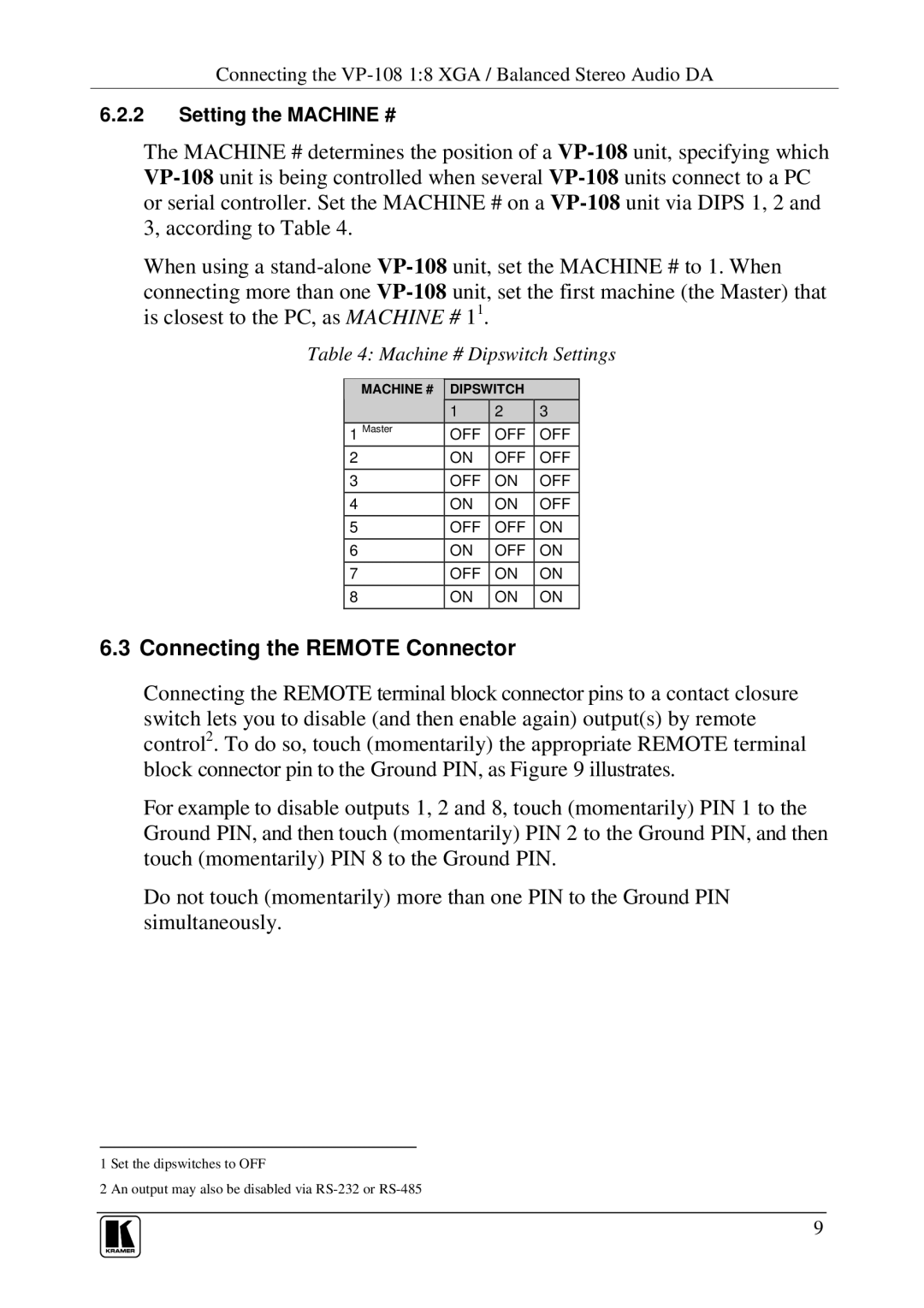
Table 4: Machine # Dipswitch Settings
MACHINE # | DIPSWITCH |
| |
| 1 | 2 | 3 |
1 Master | OFF | OFF | OFF |
2 | ON | OFF | OFF |
3 | OFF | ON | OFF |
4 | ON | ON | OFF |
5 | OFF | OFF | ON |
6 | ON | OFF | ON |
7 | OFF | ON | ON |
8ON ON ON
6.3Connecting the REMOTE Connector
Connecting the REMOTE terminal block connector pins to a contact closure switch lets you to disable (and then enable again) output(s) by remote control2. To do so, touch (momentarily) the appropriate REMOTE terminal block connector pin to the Ground PIN, as Figure 9 illustrates.
For example to disable outputs 1, 2 and 8, touch (momentarily) PIN 1 to the Ground PIN, and then touch (momentarily) PIN 2 to the Ground PIN, and then touch (momentarily) PIN 8 to the Ground PIN.
Do not touch (momentarily) more than one PIN to the Ground PIN simultaneously.
1 Set the dipswitches to OFF
2 An output may also be disabled via
9