Serial Port Pinouts
8Serial Port Pinouts
Table 7 describes the pinouts of the
Table 7: 9-Pin D-sub Serial Port Pinouts
Pin | Function |
2Receive
3Transmit
5Ground
Note: Flow control signals are not supported.
9 Table of Hex Codes for Serial Communication (Protocol 2000)
The
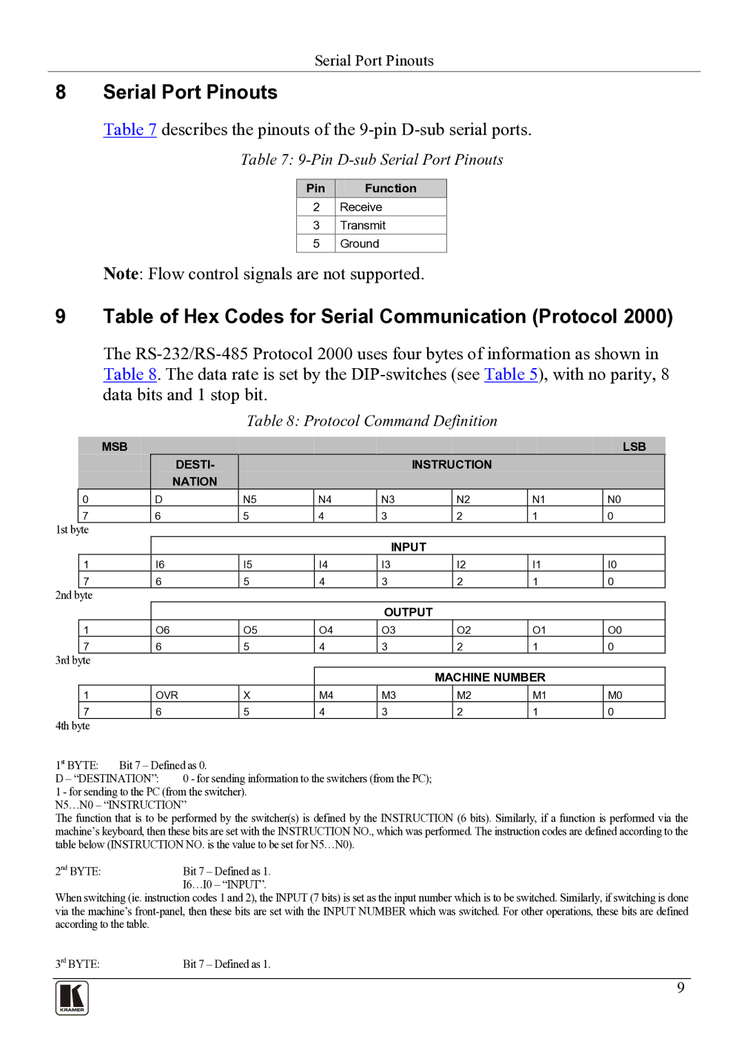
Table 8: Protocol Command Definition
| MSB |
|
|
|
|
|
|
| LSB |
|
|
|
| DESTI- |
|
|
| INSTRUCTION |
|
|
|
|
|
| NATION |
|
|
|
|
|
|
|
0 |
| D |
| N5 | N4 | N3 | N2 | N1 | N0 |
|
7 | 6 | 5 | 4 | 3 | 2 | 1 | 0 |
| ||
1st byte
1
7
2nd byte
1
7
3rd byte
1
7
4th byte
INPUT
I6 | I5 | I4 | I3 | I2 | I1 | I0 |
6 | 5 | 4 | 3 | 2 | 1 | 0 |
OUTPUT
O6 | O5 | O4 | O3 | O2 | O1 | O0 |
6 | 5 | 4 | 3 | 2 | 1 | 0 |
|
|
|
| MACHINE NUMBER |
| ||
OVR | X | M4 | M3 |
| M2 | M1 | M0 |
6 | 5 | 4 | 3 |
| 2 | 1 | 0 |
1st BYTE: | Bit 7 – Defined as 0. | |
D – “DESTINATION”: | 0 - for sending information to the switchers (from the PC); | |
1 - for sending to the PC (from the switcher). N5…N0 – “INSTRUCTION”
The function that is to be performed by the switcher(s) is defined by the INSTRUCTION (6 bits). Similarly, if a function is performed via the machine’s keyboard, then these bits are set with the INSTRUCTION NO., which was performed. The instruction codes are defined according to the table below (INSTRUCTION NO. is the value to be set for N5…N0).
2nd BYTE: | Bit 7 – Defined as 1. |
| I6…I0 – “INPUT”. |
When switching (ie. instruction codes 1 and 2), the INPUT (7 bits) is set as the input number which is to be switched. Similarly, if switching is done via the machine’s
3rd BYTE: | Bit 7 – Defined as 1. |
9