Setting the
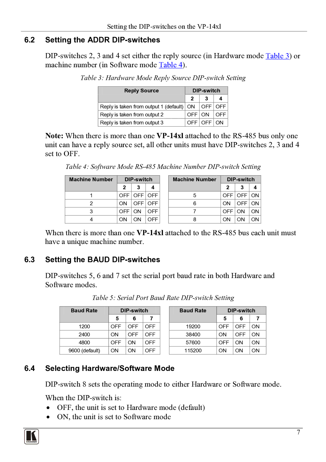
6.2Setting the ADDR DIP-switches
Table 3: Hardware Mode Reply Source DIP-switch Setting
Reply Source |
| ||
| 2 | 3 | 4 |
Reply is taken from output 1 (default) | ON | OFF | OFF |
Reply is taken from output 2 | OFF | ON | OFF |
Reply is taken from output 3 | OFF | OFF | ON |
Note: When there is more than one
Table 4: Software Mode
Machine Number | |||
| 2 | 3 | 4 |
1 | OFF | OFF | OFF |
2 | ON | OFF | OFF |
3 | OFF | ON | OFF |
4 | ON | ON | OFF |
Machine Number | |||
| 2 | 3 | 4 |
5 | OFF | OFF | ON |
6 | ON | OFF | ON |
7 | OFF | ON | ON |
8 | ON | ON | ON |
When there is more than one
6.3Setting the BAUD DIP-switches
Table 5: Serial Port Baud Rate DIP-switch Setting
Baud Rate | |||
| 5 | 6 | 7 |
1200 | OFF | OFF | OFF |
2400 | ON | OFF | OFF |
4800 | OFF | ON | OFF |
9600 (default) | ON | ON | OFF |
Baud Rate | |||
| 5 | 6 | 7 |
19200 | OFF | OFF | ON |
38400 | ON | OFF | ON |
57600 | OFF | ON | ON |
115200 | ON | ON | ON |
6.4Selecting Hardware/Software Mode
•OFF, the unit is set to Hardware mode (default)
•ON, the unit is set to Software mode
7