Defining the
4Defining the VP-14xl RS-232 Port Extender
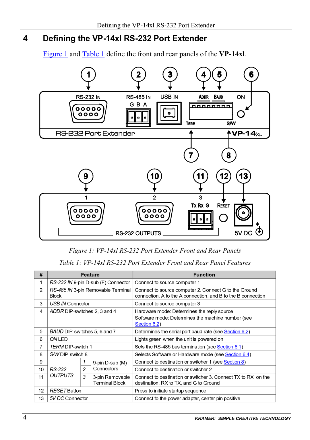
Figure 1 and Table 1 define the front and rear panels of the VP-14xl.
Figure 1: VP-14xl RS-232 Port Extender Front and Rear Panels
Table 1: VP-14xl RS-232 Port Extender Front and Rear Panel Features
| # |
| Feature |
|
| Function |
| ||
| 1 | Connect to source computer 1 |
| ||||||
| 2 | Connect to source computer 2. Connect G to the Ground |
| ||||||
|
| Block |
|
|
| connection, A to the A connection, and B to the B connection |
| ||
| 3 | USB IN Connector |
| Connect to source computer 3 |
| ||||
| 4 | ADDR | Hardware mode: Determines the reply source |
| |||||
|
|
|
|
|
| Software mode: Determines the machine number (see |
| ||
|
|
|
|
|
|
| Section 6.2) |
| |
|
|
|
|
|
|
|
|
| |
| 5 | BAUD | Determines the serial port baud rate (see Section 6.2) |
| |||||
| 6 | ON LED |
|
|
| Lights green when the unit is powered on |
| ||
| 7 | TERM |
| Sets the |
| ||||
| 8 | S/W |
| Selects Software or Hardware mode (see Section 6.4) |
| ||||
| 9 |
| 1 |
| Connect to destination or switcher 1 (see Section 8) |
| |||
| 10 | 2 |
| Connectors | Connect to destination or switcher 2 |
| |||
| 11 | OUTPUTS | 3 |
| Connect to destination or switcher 3. Connect TX to RX on the |
| |||
|
|
|
|
| Terminal Block | destination, RX to TX, and G to Ground |
| ||
| 12 | RESET Button |
| Press to initiate startup sequence |
| ||||
| 13 | 5V DC Connector |
| Connect to the power adapter, center pin positive |
| ||||
|
|
|
|
|
|
|
|
|
|
4 |
|
|
|
|
|
|
| KRAMER: SIMPLE CREATIVE TECHNOLOGY | |
