4. LED Indicators
4.1 LED Panel
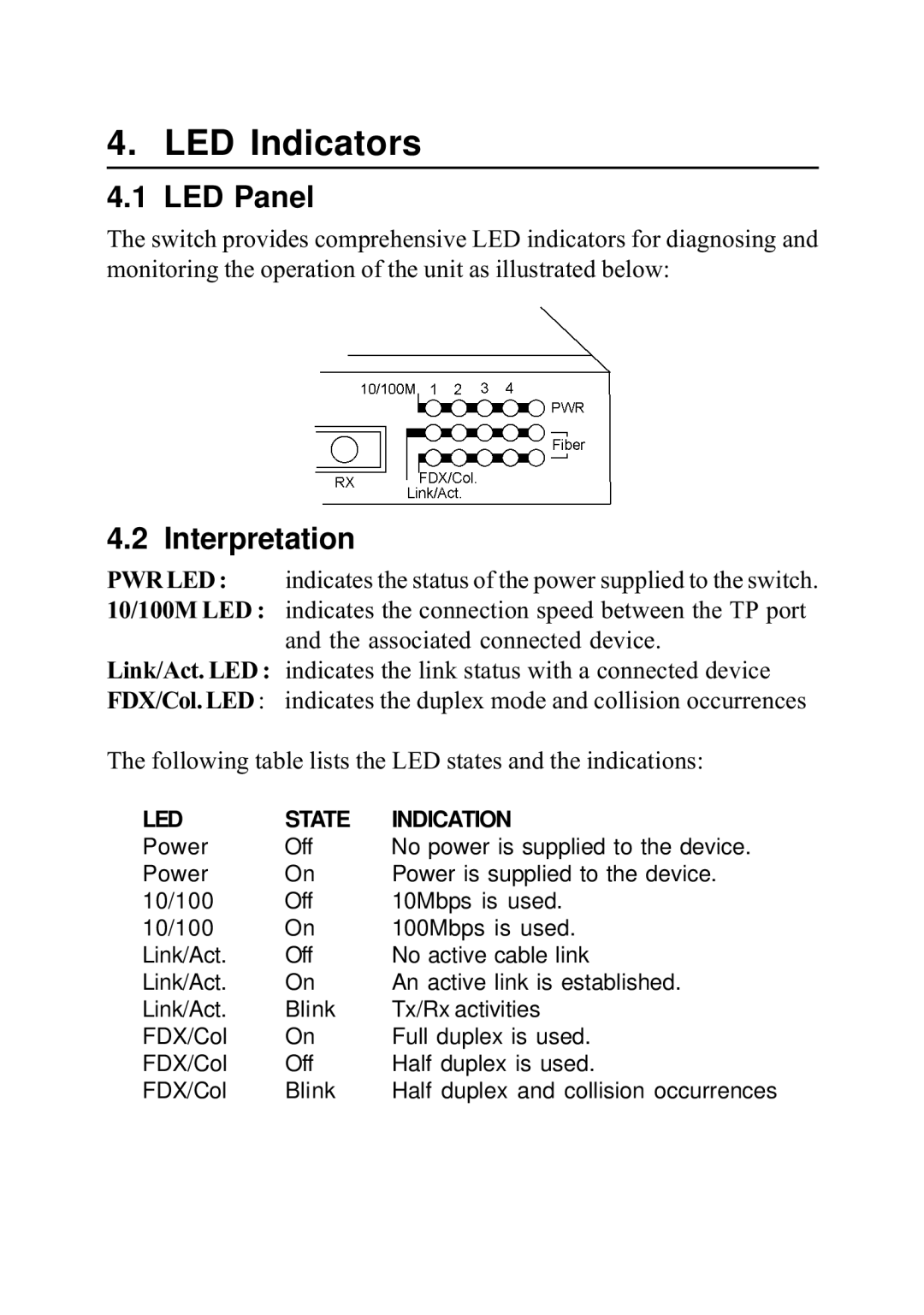
The switch provides comprehensive LED indicators for diagnosing and monitoring the operation of the unit as illustrated below:
4.2 Interpretation
PWR LED : indicates the status of the power supplied to the switch.
10/100M LED : indicates the connection speed between the TP port and the associated connected device.
Link/Act. LED : indicates the link status with a connected device
FDX/Col. LED : indicates the duplex mode and collision occurrences
The following table lists the LED states and the indications:
LED | STATE | INDICATION |
Power | Off | No power is supplied to the device. |
Power | On | Power is supplied to the device. |
10/100 | Off | 10Mbps is used. |
10/100 | On | 100Mbps is used. |
Link/Act. | Off | No active cable link |
Link/Act. | On | An active link is established. |
Link/Act. | Blink | Tx/Rx activities |
FDX/Col | On | Full duplex is used. |
FDX/Col | Off | Half duplex is used. |
FDX/Col | Blink | Half duplex and collision occurrences |