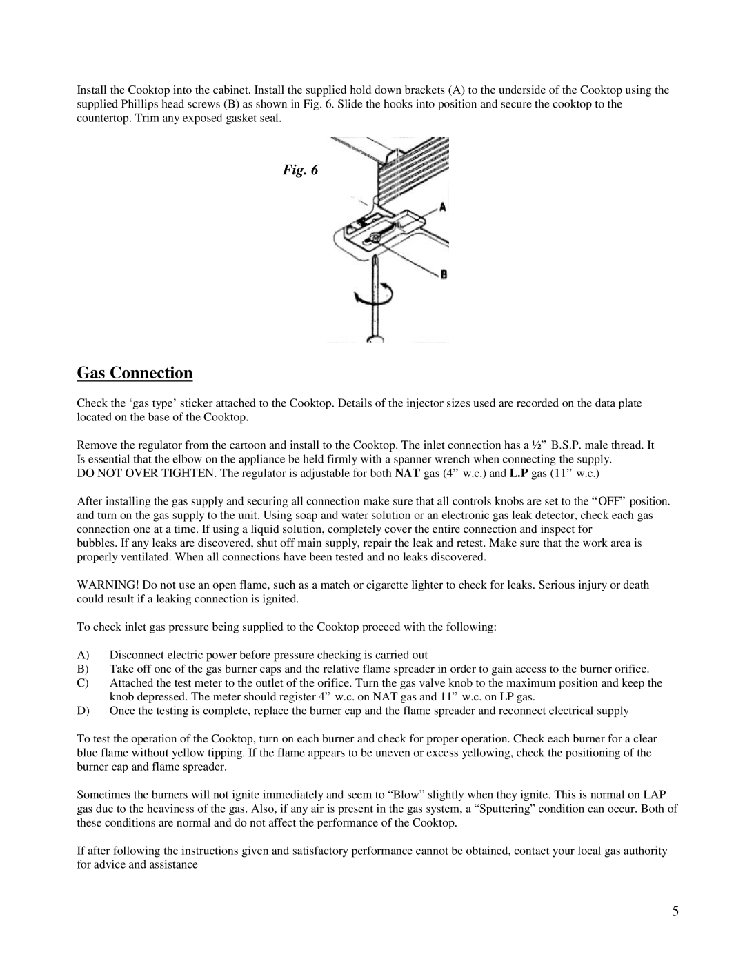
Install the Cooktop into the cabinet. Install the supplied hold down brackets (A) to the underside of the Cooktop using the supplied Phillips head screws (B) as shown in Fig. 6. Slide the hooks into position and secure the cooktop to the countertop. Trim any exposed gasket seal.
Fig. 6
Gas Connection
Check the ‘gas type’sticker attached to the Cooktop. Details of the injector sizes used are recorded on the data plate located on the base of the Cooktop.
Remove the regulator from the cartoon and install to the Cooktop. The inlet connection has a ½” B.S.P. male thread. It Is essential that the elbow on the appliance be held firmly with a spanner wrench when connecting the supply.
DO NOT OVER TIGHTEN. The regulator is adjustable for both NAT gas (4” w.c.) and L.P gas (11” w.c.)
After installing the gas supply and securing all connection make sure that all controls knobs are set to the “OFF” position. and turn on the gas supply to the unit. Using soap and water solution or an electronic gas leak detector, check each gas connection one at a time. If using a liquid solution, completely cover the entire connection and inspect for
bubbles. If any leaks are discovered, shut off main supply, repair the leak and retest. Make sure that the work area is properly ventilated. When all connections have been tested and no leaks discovered.
WARNING! Do not use an open flame, such as a match or cigarette lighter to check for leaks. Serious injury or death could result if a leaking connection is ignited.
To check inlet gas pressure being supplied to the Cooktop proceed with the following:
A)Disconnect electric power before pressure checking is carried out
B)Take off one of the gas burner caps and the relative flame spreader in order to gain access to the burner orifice.
C)Attached the test meter to the outlet of the orifice. Turn the gas valve knob to the maximum position and keep the knob depressed. The meter should register 4” w.c. on NAT gas and 11” w.c. on LP gas.
D)Once the testing is complete, replace the burner cap and the flame spreader and reconnect electrical supply
To test the operation of the Cooktop, turn on each burner and check for proper operation. Check each burner for a clear blue flame without yellow tipping. If the flame appears to be uneven or excess yellowing, check the positioning of the burner cap and flame spreader.
Sometimes the burners will not ignite immediately and seem to “Blow” slightly when they ignite. This is normal on LAP gas due to the heaviness of the gas. Also, if any air is present in the gas system, a “Sputtering” condition can occur. Both of these conditions are normal and do not affect the performance of the Cooktop.
If after following the instructions given and satisfactory performance cannot be obtained, contact your local gas authority for advice and assistance
5