Land Pride | Table of Contents |
Section 1: Assembly and Set-up
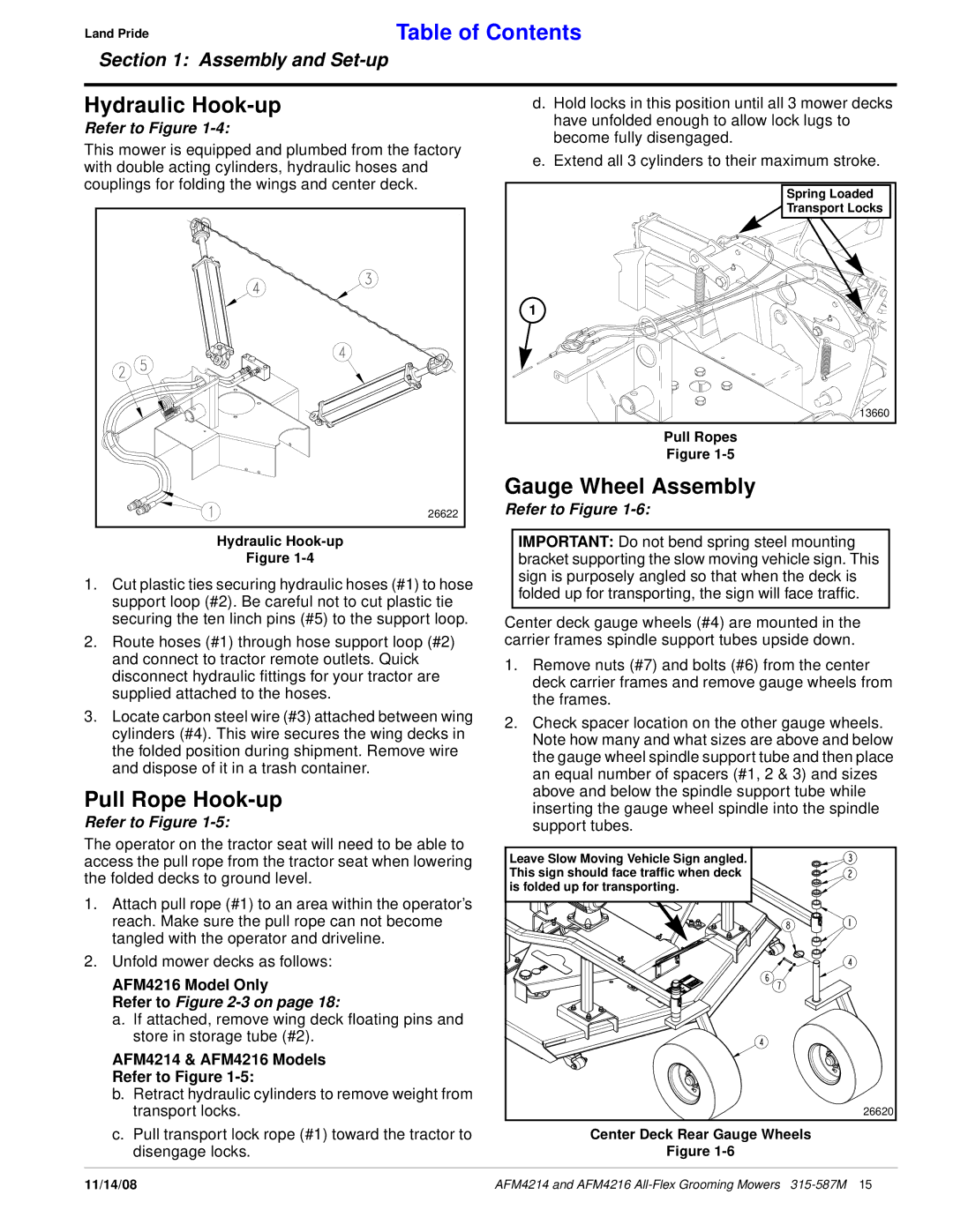
Hydraulic
Figure
1.Cut plastic ties securing hydraulic hoses (#1) to hose support loop (#2). Be careful not to cut plastic tie securing the ten linch pins (#5) to the support loop.
2.Route hoses (#1) through hose support loop (#2) and connect to tractor remote outlets. Quick disconnect hydraulic fittings for your tractor are supplied attached to the hoses.
3.Locate carbon steel wire (#3) attached between wing cylinders (#4). This wire secures the wing decks in the folded position during shipment. Remove wire and dispose of it in a trash container.
Pull Rope Hook-up
Refer to Figure 1-5:
The operator on the tractor seat will need to be able to access the pull rope from the tractor seat when lowering the folded decks to ground level.
1.Attach pull rope (#1) to an area within the operator’s reach. Make sure the pull rope can not become tangled with the operator and driveline.
2.Unfold mower decks as follows:
AFM4216 Model Only
Refer to Figure 2-3 on page 18:
a.If attached, remove wing deck floating pins and store in storage tube (#2).
AFM4214 & AFM4216 Models
Refer to Figure 1-5:
b.Retract hydraulic cylinders to remove weight from transport locks.
c.Pull transport lock rope (#1) toward the tractor to disengage locks.
IMPORTANT: Do not bend spring steel mounting bracket supporting the slow moving vehicle sign. This sign is purposely angled so that when the deck is folded up for transporting, the sign will face traffic.
Center deck gauge wheels (#4) are mounted in the carrier frames spindle support tubes upside down.
1.Remove nuts (#7) and bolts (#6) from the center deck carrier frames and remove gauge wheels from the frames.
2.Check spacer location on the other gauge wheels. Note how many and what sizes are above and below the gauge wheel spindle support tube and then place an equal number of spacers (#1, 2 & 3) and sizes above and below the spindle support tube while inserting the gauge wheel spindle into the spindle support tubes.
Leave Slow Moving Vehicle Sign angled. This sign should face traffic when deck is folded up for transporting.
26620
Center Deck Rear Gauge Wheels
Figure
11/14/08 | AFM4214 and AFM4216 |