2Hardware Setup
1.Connect the power supply to the LAVA
2.Connect an Ethernet
Network status is indicated by two LEDs on the
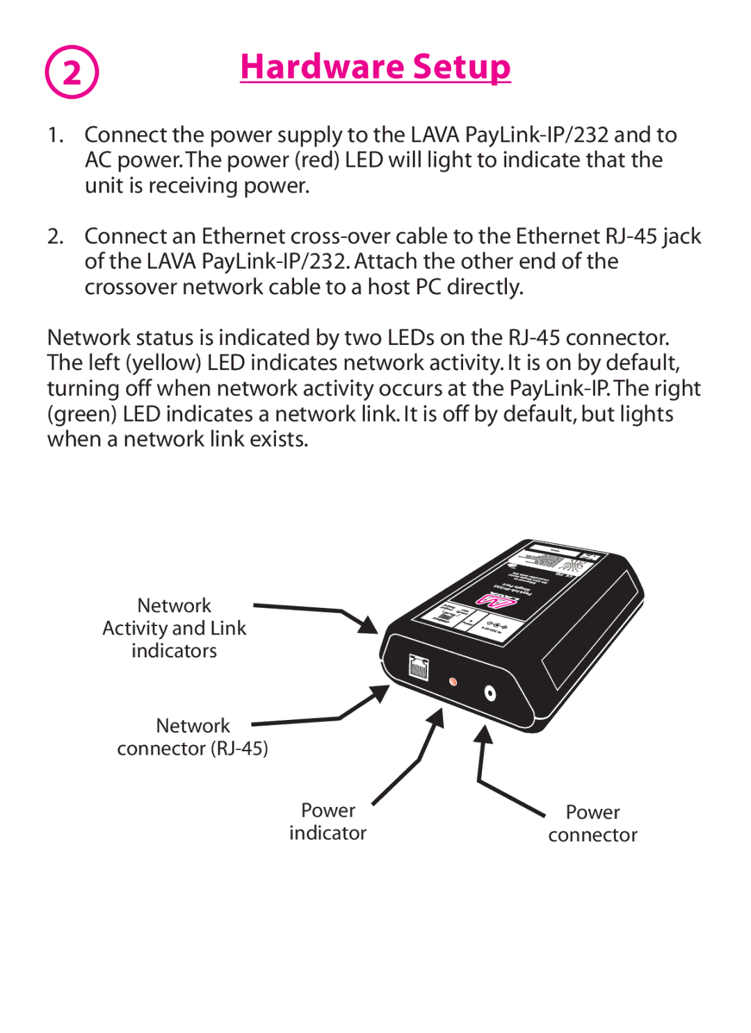
Network
Activity and Link
indicators
Network ![]() connector
connector
Power | Power |
indicator | connector |
1.Connect the power supply to the LAVA
2.Connect an Ethernet
Network status is indicated by two LEDs on the
Network
Activity and Link
indicators
Network ![]() connector
connector
Power | Power |
indicator | connector |