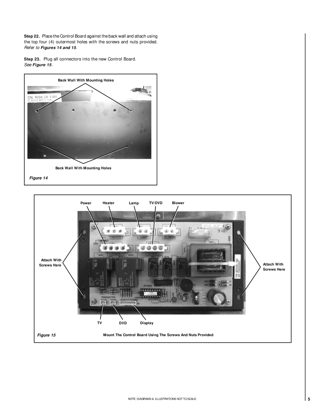
Step 22. Place the Control Board against the back wall and attach using the top four (4) outermost holes with the screws and nuts provided. Refer to Figures 14 and 15.
Step 23. Plug all connectors into the new Control Board.
See Figure 15.
Back Wall With Mounting Holes
Back Wall With Mounting Holes
Figure 14
Power | Heater | Lamp | TV/DVD | Blower |
Attach With
Screws HereAttach With
Screws Here
TVDVD Display
Figure 15 | Mount The Control Board Using The Screws And Nuts Provided |
NOTE: DIAGRAMS & ILLUSTRATIONS NOT TO SCALE. | 5 |