INSTALLATION Combustible Wall Chimney Connector Pass-Throughs

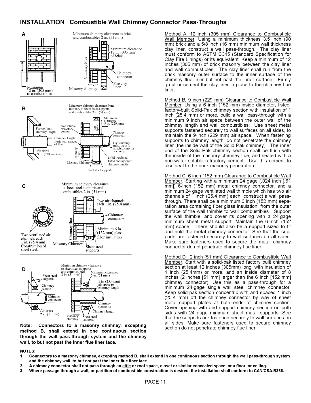
A

B

C

D

Note: Connectors to a masonry chimney, excepting method B, shall extend in one continuous section through the wall pass-through system and the chimney wall, to but not past the inner flue liner face.

Method A. 12 inch (305 mm) Clearance to Combustible Wall Member: Using a minimum thickness 3.5 inch (90

mm)brick and a 5/8 inch (16 mm) minimum wall thickness clay liner, construct a wall pass-through. The clay liner must conform to ASTM C315 (Standard Specification for Clay Fire Linings) or its equivalent. Keep a minimum of 12 inches (305 mm) of brick masonry between the clay liner and wall combustibles. The clay liner shall run from the brick masonry outer surface to the inner surface of the chimney flue liner but not past the inner surface. Firmly grout or cement the clay liner in place to the chimney flue liner.

Method B. 9 inch (229 mm) Clearance to Combustible Wall Member: Using a 6 inch (152 mm) inside diameter, listed, factory-built Solid-Pak chimney section with insulation of 1 inch (25.4 mm) or more, build a wall pass-through with a minimum 9 inch air space between the outer wall of the chimney length and wall combustibles. Use sheet metal supports fastened securely to wall surfaces on all sides, to maintain the 9-inch (229 mm) air space. When fastening supports to chimney length, do not penetrate the chimney liner (the inside wall of the Solid-Pak chimney). The inner end of the Solid-Pak chimney section shall be flush with the inside of the masonry chimney flue, and sealed with a non-water soluble refractory cement. Use this cement to also seal to the brick masonry penetration.

Method C. 6 inch (152 mm) Clearance to Combustible Wall Member: Starting with a minimum 24 gage (.024 inch [.61 mm]) 6-inch (152 mm) metal chimney connector, and a minimum 24 gage ventilated wall thimble which has two air channels of 1 inch (25.4 mm) each, construct a wall pass- through. There shall be a minimum 6 inch (152 mm) sepa- ration area containing fiber glass insulation, from the outer surface of the wall thimble to wall combustibles. Support the wall thimble, and cover its opening with a 24-gage minimum sheet metal support. Maintain the 6-inch (152

mm)space. There should also be a support sized to fit and hold the metal chimney connector. See that the sup- ports are fastened securely to wall surfaces on all sides. Make sure fasteners used to secure the metal chimney connector do not penetrate chimney flue liner.

Method D. 2 inch (51 mm) Clearance to Combustible Wall Member: Start with a solid-pak listed factory built chimney section at least 12 inches (305mm) long, with insulation of 1 inch (25.4mm) or more, and an inside diameter of 8 inches (2 inches [51 mm] larger than the 6 inch [152 mm] chimney connector). Use this as a pass-through for a minimum 24-gage single wall steel chimney connector. Keep solid-pak section concentric with and spaced 1 inch (25.4 mm) off the chimney connector by way of sheet metal support plates at both ends of chimney section. Cover opening with and support chimney section on both sides with 24 gage minimum sheet metal supports. See that the supports are fastened securely to wall surfaces on all sides. Make sure fasteners used to secure chimney section do not penetrate chimney flue liner.

NOTES:

1.Connectors to a masonry chimney, excepting method B, shall extend in one continuous section through the wall pass-through system and the chimney wall, to but not past the inner flue liner face.

2.A chimney connector shall not pass through an attic or roof space, closet or similar concealed space, or a floor, or ceiling.

3.Where passage through a wall, or partition of combustible construction is desired, the installation shall conform to CAN/CSA-B365.

PAGE 11

Page 11
Image 11
Lennox Hearth T150C operation manual

T150C specifications

The Lennox Hearth T150C is a premium heating solution that epitomizes efficiency, reliability, and modern design. This wood-burning fireplace insert is crafted to enhance both the aesthetic appeal and functional warmth of any living space. With its elegant look and cutting-edge technologies, the T150C provides homeowners with an exceptional heating experience.

One of the standout features of the Lennox Hearth T150C is its high-efficiency combustion system. This system is designed to maximize heat output while minimizing emissions, making it an environmentally friendly choice for wood burning. The insert boasts an impressive efficiency rating, allowing homeowners to utilize less wood while still achieving a warm and cozy atmosphere. This efficient burning technology also means that less smoke and ash are produced, making it easier to maintain and keep clean.

The T150C features a large viewing window, framed by a sleek cast iron door, which allows for an unobstructed view of the mesmerizing flames. The design not only enhances the fireplace’s aesthetic appeal but also provides an effective heat radiating feature. The ceramic glass window can withstand high temperatures, ensuring both safety and durability while allowing the beauty of the fire to be enjoyed from several angles.

Additionally, the T150C is designed with adjustable air controls that allow users to customize the fire's heat output and burn time. This feature provides flexibility in managing the environment and comfort levels in the home. Its intuitive design makes it easy for anyone to operate, ensuring that users can enjoy a warm fire with minimal effort.

Another highlight of the Lennox Hearth T150C is its compact design, making it suitable for various room sizes. Its streamlined look and modern finish allow it to seamlessly integrate with both traditional and contemporary home decors.

Overall, the Lennox Hearth T150C wood-burning fireplace insert combines efficiency, elegance, and advanced heating technology, making it an ideal choice for anyone looking to enhance their home with a reliable and attractive source of warmth. With its blend of functionality and style, the T150C sets a standard for wood-burning fireplaces in the market.