System Operation

IMPORTANT

Some scroll compressor have internal vacuum protector that will unload scrolls when suction pressure goes below 20 psig. A hissing sound will be heard when the compressor is running unloaded. Protector will reset when low pressure in system is raised above 40 psig. DO NOT REPLACE COMPRESSOR.

High Pressure Switch (S4)

This unit is equipped with a auto-reset high pressure switch (single−pole, single−throw) which is located on the liquid line. The switch shuts off the compressor when discharge pressure rises above the factory setting. High Pressure (auto reset) − trip at 590 psig, reset at 418 psig.

Low Pressure Switch (S87)

This unit is equipped an auto−reset low pressure switch which is located on the vapor line. The switch shuts off the compressor when the vapor pressure falls below the factory setting. Low Pressure (auto reset) − trip at 25 psig, reset at 40 psig.

Low Pressure Switch Bypass (S41) (Optional)

For use in applications where the heat pump is operated in outdoor ambient temperatures below 15°F.

SPrevents nuisance trips form the low pressure switch

SWired in parallel with the low pressure switch

Thermal Protection Switch (S173)

Mounted

Some units are equipped with a compressor mounted normally closed temperature switch that prevents compressor damage due to overheating caused by internal friction. The switch is located on top of the compressor casing (see figure 1). This switch senses the compressor casing temperature and opens at 239−257°F (115°C−125°C) to shut off compressor operation. The auto−reset switch closes when the compressor casing temperature falls to 151−187°F (66°C−86°C), and the compressor is re−energized. This single−pole, single−throw (SPST) bi−metallic switch is wired in series with the 24V Y input signal to control compressor operation.

Crankcase Thermostat (S40) (−042, −048 and −060

Units Only)

The reference models are equipped with a 70 watt, belly band type crankcase heater. HR1 prevents liquid from accumulating in the compressor. HR1 is controlled by a thermostat located on the liquid line. When liquid line temperature drops below 50° F the thermostat closes energizing HR1. The thermostat will open, de−energizing HR1 once liquid line temperature reaches 70° F .

Defrost Thermostat (S6)

The defrost thermostat is located on the liquid line between the check/expansion valve and the distributor. When defrost thermostat senses 42°F (5.5°C) or cooler, the thermostat contacts close and send a signal to the defrost control to start the defrost timing. It also terminates defrost when the liquid line warms up to 70°F (21°C).

Bi−Flow Liquid Line Filter Drier

The unit is equipped with a large−capacity biflow filter drier which keeps the system clean and dry. If replacement is necessary, order another of the same design and capacity. The replacement filter drier must be suitable for use with HFC−410A refrigerant.

Defrost System

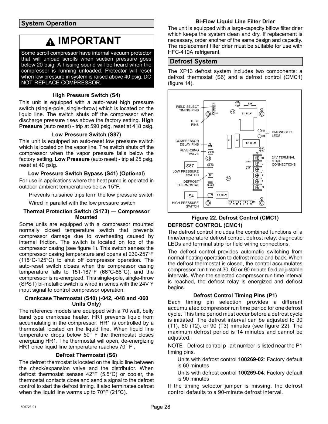
The XP13 defrost system includes two components: a defrost thermostat (S6) and a defrost control (CMC1) (figure 14).

FIELD SELECT


TIMING PINS


TEST


PINS


DIAGNOSTIC


LEDS

COMPRESSOR


DELAY PINS


REVERSING


VALVE


24V TERMINAL


STRIP

S87

CONNECTIONS


LOW PRESSURE


SWITCH


DEFROST


THERMOSTAT


S4


HIGH PRESSURE


SWITCH


Figure 22. Defrost Control (CMC1)

DEFROST CONTROL (CMC1)

The defrost control includes the combined functions of a time/temperature defrost control, defrost relay, diagnostic LEDs and terminal strip for field wiring connections.

The defrost control provides automatic switching from normal heating operation to defrost mode and back. When the defrost thermostat is closed, the control accumulates compressor run time at 30, 60 or 90 minute field adjustable intervals. When the selected compressor run time interval is reached, the defrost relay is energized and defrost begins.

Defrost Control Timing Pins (P1)

Each timing pin selection provides a different accumulated compressor run time period for one defrost cycle. This time period must occur before a defrost cycle is initiated. The defrost interval can be adjusted to 30 (T1), 60 (T2), or 90 (T3) minutes (see figure 22). The maximum defrost period is 14 minutes and cannot be adjusted.

NOTE part number is listed near the P1 timing pins.

SUnits with defrost control 100269−02: Factory default is 60 minutes

SUnits with defrost control 100269−04: Factory default is 90 minutes

If the timing selector jumper is missing, the defrost control defaults to a 90−minute defrost interval.

506728−01

Page 28

Page 28
Image 28
Lennox International Inc 06/11 50672801 installation instructions System Operation, Defrost System, Defrost Control CMC1

LENNOX Elite Series XP13 Units HEAT PUMPS, 06/11 50672801 specifications

Lennox International Inc., a leading name in the HVAC (heating, ventilation, and air conditioning) industry, has a reputation for delivering high-quality and energy-efficient systems. One of the standout products in their lineup is the Lennox Elite Series XP13 heat pump, model number 50672801. This heat pump is designed to provide exceptional comfort throughout the year while offering efficiency and reliability that homeowners can depend on.

The Lennox Elite Series XP13 heat pump features a compact design that makes it suitable for various outdoor spaces. One of its main characteristics is its efficiency, boasting a SEER (Seasonal Energy Efficiency Ratio) rating of up to 16 and an HSPF (Heating Seasonal Performance Factor) of up to 9. This means that the XP13 can help reduce energy bills, making it an eco-friendly choice for homeowners looking to minimize their carbon footprint.

This heat pump utilizes advanced technology to ensure optimal performance. The XP13 is equipped with a scroll compressor, which operates quietly and efficiently compared to traditional compressors. This feature ensures a more reliable and consistent temperature control, which translates to enhanced comfort levels in the home. Moreover, the XP13 is designed with a sound-dampening system that reduces operational noise, making it one of the quieter options in the market.

Another key aspect of the XP13 heat pump is its innovative use of advanced coil technology. The unit's coils are made from high-grade aluminum, which promotes superior heat exchange and improves overall efficiency. In addition, the XP13 is designed with a built-in filter drier that helps remove moisture and contaminants from the refrigerant, protecting the system from potential damage and enhancing its lifespan.

The XP13 model is compatible with the iComfort S30 smart thermostat, allowing users to control their home’s temperature remotely. This smart technology provides energy-saving options and real-time updates, ensuring that homeowners can optimize their HVAC systems for both comfort and efficiency.

Overall, the Lennox Elite Series XP13 heat pump, model 50672801, exemplifies a commitment to delivering high-performance heating and cooling solutions. With its energy-efficient design, advanced technologies, and features aimed at enhancing user comfort and convenience, the XP13 remains a top choice among homeowners looking for a reliable and effective heat pump system.