
EL280DF specifications
Lennox International Inc. has been a leader in the HVAC (Heating, Ventilation, and Air Conditioning) industry for decades, consistently delivering high-quality and energy-efficient products. Among their lineup, the Lennox EL280DF Gas Furnace stands out as an excellent option for homeowners seeking reliable heating solutions.The EL280DF is a two-stage gas furnace that offers improved efficiency and comfort, making it an ideal choice for moderate climates. One of the main features of the EL280DF is its energy efficiency, boasting an AFUE (Annual Fuel Utilization Efficiency) rating of up to 80%. This means that a significant portion of the fuel consumed is converted into heating energy, resulting in lower energy bills and reduced environmental impact.
Another noteworthy characteristic of the EL280DF is its quiet operation. Equipped with advanced sound-dampening technologies, the furnace operates with minimal noise, ensuring that your home remains a serene environment. This is especially important during the colder months when the furnace is often in frequent use.
The EL280DF also employs a two-stage heating system, which allows it to operate at a lower capacity during milder temperatures and ramp up to full capacity during the coldest days. This feature not only enhances comfort by maintaining a more consistent temperature but also contributes to energy savings by reducing unnecessary energy consumption.
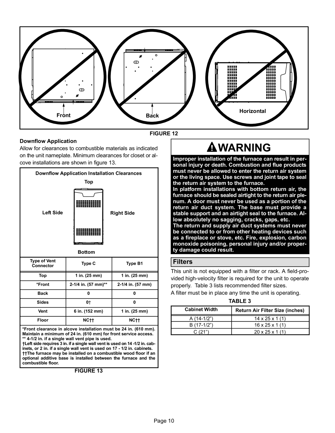
In terms of installation, the EL280DF is designed for flexibility. It can be configured for various types of homes and installations, making it suitable for both new constructions and system replacements. Its compact size allows it to fit in tight spaces, providing versatility in home design.
Moreover, the EL280DF is equipped with a durable heat exchanger that ensures longevity and reliability. Lennox has also included features like a self-diagnostic control board, making troubleshooting easier and enhancing the overall reliability of the system.
In conclusion, the Lennox EL280DF Gas Furnace is a remarkable combination of efficiency, quiet operation, and versatility. With its two-stage heating capabilities and advanced technologies, it stands as a solid choice for homeowners looking to invest in a durable and energy-efficient heating solution. Whether building a new home or upgrading an old system, the EL280DF promises comfort and reliability during the coldest months of the year.