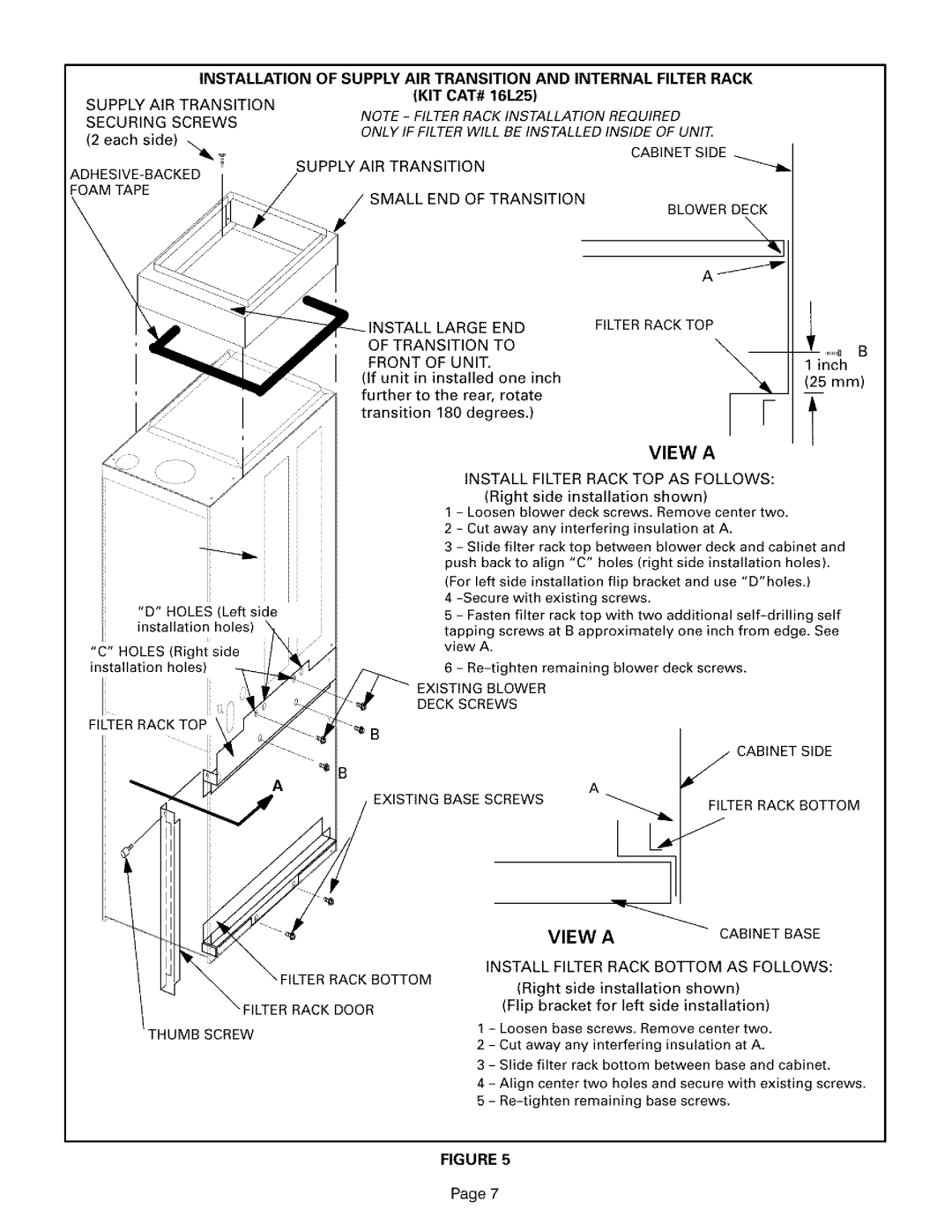
INSTALLATION OF SUPPLY AIR TRANSITION AND INTERNAL FILTER RACK
SUPPLY AIR TRANSITION | (KIT CAT# 16L25) |
SECURING SCREWS | NOTE - FILTERRACK INSTALLATION REQUIRED |
| ONLY IF FILTER WILL BE INSTALLED INSIDE OF UNIT |
(2 each side) ,_
T
FOAM TAPE
SUPPLY AIR TRANSITION | CABINET SIDE |
;MALL END OF TRANSITION
BLOWER DECK
\
;TALL LARGE END | FILTER RACK TOP | |
OF TRANSITION TO | ,I,I,IB }3 | |
FRONT OF UNIT. | ||
1 inch | ||
(If unit in installed one inch | (25 mm) | |
further to the rear, rotate | ||
| ||
transition 180 degrees.) |
|
"D" HOLES (Left side installation holes)
"C" HOLES (Right side installation holes
FILTER RACK TOP
|
|
|
|
|
| VIEW | A |
|
| |
|
| INSTALL FILTER RACK TOP AS FOLLOWS: |
| |||||||
|
| (Right | side | installation |
| shown) |
|
|
| |
1 | - Loosen blower | deck | screws. | Remove center two. |
| |||||
2 | - | Cut away | any | interfering | insulation | at A. |
|
| ||
3 | - | Slide filter | rack top between | blower | deck | and cabinet and | ||||
push back to align "C" holes (right side installation holes). | ||||||||||
(For left side installation flip bracket and use "D'holes.) |
| |||||||||
4 |
|
|
|
| ||||||
5 | - | Fasten filter rack top | with | two additional | self | |||||
tapping screws at B approximately one inch from edge. See | ||||||||||
view A. |
|
|
|
|
|
|
|
| ||
6 | - | remaining | blower | deck | screws. |
| ||||
EXISTING BLOWER |
|
|
|
|
|
|
| |||
DECK SCREWS |
|
|
|
|
|
|
|
| ||
|
|
|
|
|
|
|
| // | CABINET | SIDE |
EXISTING BASE SCREWS | A |
|
|
|
|
|
| |||
|
|
|
|
|
|
| ||||
|
|
|
|
|
|
|
| J |
|
|
|
|
|
|
| "_ |
|
| FILTER RACK BOTTOM | ||
|
|
|
|
|
|
| 1 |
|
|
|
|
|
| VIEW | A |
|
| CABINETBASE | |||
"FILTER RACK BOTTOM "FILTER RACK DOOR
THUMB SCREW
INSTALL FILTER RACK BOTTOM AS FOLLOWS:
(Right side installation shown) (Flip bracket for left side installation)
1 - Loosen base screws. Remove center two.
2 - Cut away any interfering insulation at A.
3 - Slide filter rack bottom between base and cabinet,
4 - Align center two holes and secure with existing screws. 5 -
FIGURE 5
Page 7
