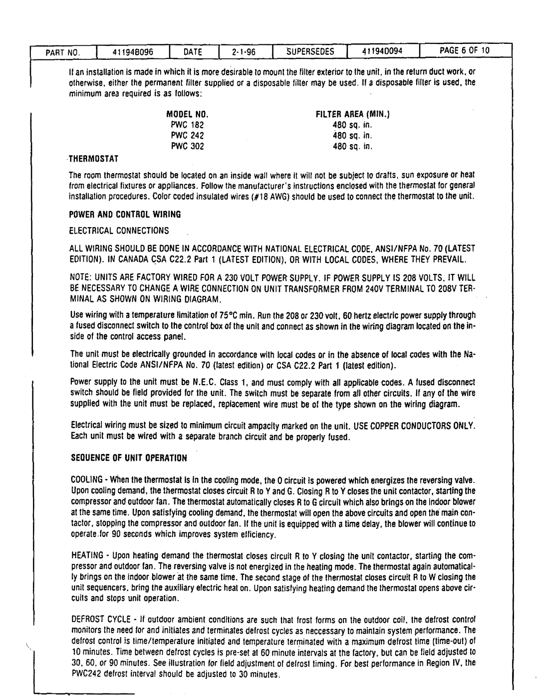
PWC18E14.7, PWC18E4.8, PWC182, PWC24E7.2, PVVC24ElO.7 specifications
Lennox International Inc. is a leading provider of innovative heating, ventilation, and air conditioning (HVAC) solutions. Among its diverse range of products, the company offers various models of packaged water chillers designed for efficiency, performance, and reliability in commercial applications. The PWC18E10.7, PWC302, PWGI8E7.2, PWC182, and PWC242 are notable examples of Lennox's commitment to quality and advanced technology in packaged water chillers.The Lennox PWC18E10.7 is a high-efficiency chiller featuring a compact design, making it suitable for space-constrained environments. With a cooling capacity of 18 tons, this model utilizes a scroll compressor for reliable operation and low energy consumption. Its advanced microchannel coil technology enhances heat transfer efficiency, allowing for better cooling performance with a reduced refrigerant charge.
The PWC302 is another robust offering, boasting a cooling capacity of 30 tons. This model is designed for outdoor installation, equipped with fully controllable variable-speed fans that adapt to varying load conditions. The PWC302 is notable for its low noise levels, making it ideal for applications where sound restrictions are paramount. Its advanced controls also provide flexibility in managing energy usage, further enhancing its appeal for eco-conscious businesses.
The PWGI8E7.2 is distinguished by its inverter-driven compressor, which allows for precise temperature control and enhanced efficiency. This model, with an 8-ton cooling capacity, is particularly suited for environments requiring consistent cooling. Its compact footprint coupled with high energy efficiency ratings means it can be easily integrated into existing systems while ensuring optimal performance.
The PWC182, another capable unit, is designed with a focus on durability and ease of maintenance. Features such as a corrosion-resistant cabinet and user-friendly access panels make it a practical choice for facilities managers. The PWC182 operates quietly and efficiently, ensuring minimal disruption in operational settings.
Lastly, the PWC242 provides a larger cooling capacity of 24 tons, making it ideal for medium to large commercial spaces. Its advanced refrigerant management system optimizes performance while meeting environmental regulations. All these models incorporate advanced electronic controls, which enhance operational efficiency and provide real-time monitoring capabilities, allowing users to optimize energy consumption based on actual demand.
In summary, Lennox International offers a range of advanced packaged water chillers, including models like the PWC18E10.7, PWC302, PWGI8E7.2, PWC182, and PWC242. Each model features cutting-edge technologies aimed at delivering high efficiency, reliability, and ease of use, making them suitable choices for commercial applications seeking sustainable and effective HVAC solutions.

