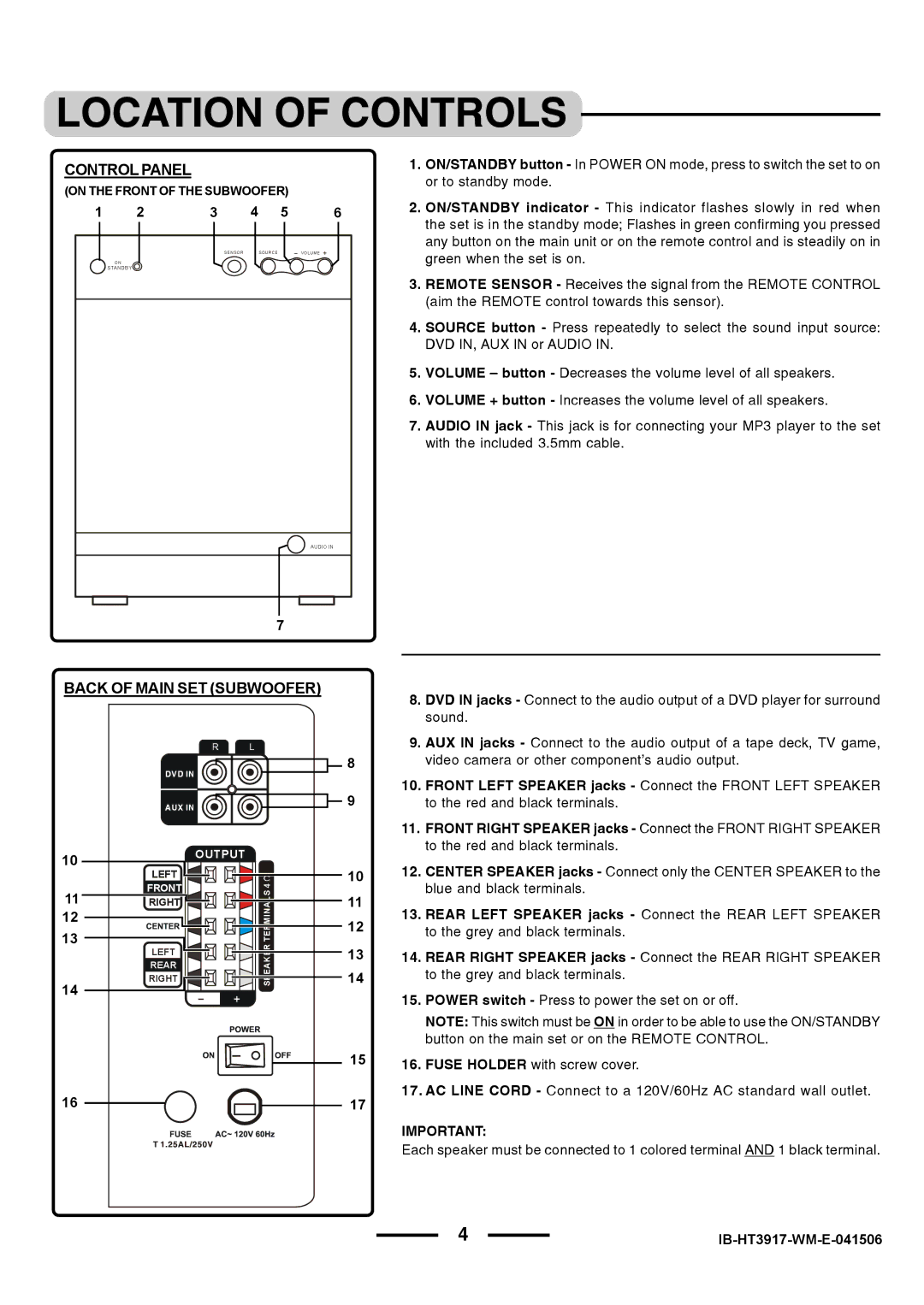
CONTROL PANEL
(ON THE FRONT OF THE SUBWOOFER)
1 | 2 | 3 | 4 | 5 | 6 |
|
| SENSOR |
| SOURCE | VOLUME |
ON
STANDBY
AUDIO IN
1.ON/STANDBY button - In POWER ON mode, press to switch the set to on or to standby mode.
2.ON/STANDBY indicator - This indicator flashes slowly in red when the set is in the standby mode; Flashes in green confirming you pressed any button on the main unit or on the remote control and is steadily on in green when the set is on.
3.REMOTE SENSOR - Receives the signal from the REMOTE CONTROL (aim the REMOTE control towards this sensor).
4.SOURCE button - Press repeatedly to select the sound input source: DVD IN, AUX IN or AUDIO IN.
5.VOLUME – button - Decreases the volume level of all speakers.
6.VOLUME + button - Increases the volume level of all speakers.
7.AUDIO IN jack - This jack is for connecting your MP3 player to the set with the included 3.5mm cable.
7
BACK OF MAIN SET (SUBWOOFER)
8. DVD IN jacks - Connect to the audio output of a DVD player for surround sound.
R L
DVD IN
AUX IN
10 |
| OUTPUT |
LEFT |
| |
| 4 | |
| FRONT | |
11 | RIGHT | TERMINALS |
12 |
|
|
13 | RIGHT | SPEAKER |
| LEFT |
|
REAR
14 | + |
|
16 ![]()
9.AUX IN jacks - Connect to the audio output of a tape deck, TV game,
8video camera or other component’s audio output.
10.FRONT LEFT SPEAKER jacks - Connect the FRONT LEFT SPEAKER
9 | to the red and black terminals. |
11.FRONT RIGHT SPEAKER jacks - Connect the FRONT RIGHT SPEAKER to the red and black terminals.
1012. CENTER SPEAKER jacks - Connect only the CENTER SPEAKER to the blue and black terminals.
11 | 13. REAR LEFT SPEAKER jacks - Connect the REAR LEFT SPEAKER | |
12 | ||
to the grey and black terminals. | ||
13 | 14. REAR RIGHT SPEAKER jacks - Connect the REAR RIGHT SPEAKER | |
14 | to the grey and black terminals. |
15. POWER switch - Press to power the set on or off.
NOTE: This switch must be ON in order to be able to use the ON/STANDBY button on the main set or on the REMOTE CONTROL.
1516. FUSE HOLDER with screw cover.
17.AC LINE CORD - Connect to a 120V/60Hz AC standard wall outlet.
IMPORTANT:
Each speaker must be connected to 1 colored terminal AND 1 black terminal.
4 |
|
