Installation
In this manual, "User" refers to whoever has access to the Network Camera, and "Administrator" refers to the person who can configure the Network Camera and grant user access to the camera.
Hardware installation
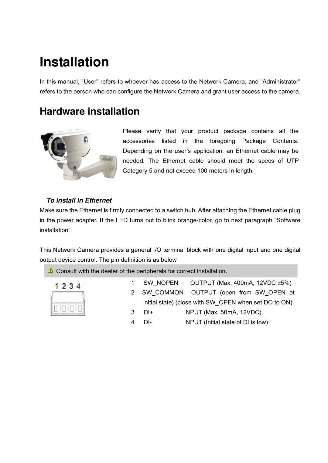
Please verify that your product package contains all the accessories listed in the foregoing Package Contents. Depending on the user’s application, an Ethernet cable may be needed. The Ethernet cable should meet the specs of UTP Category 5 and not exceed 100 meters in length.
To install in Ethernet
Make sure the Ethernet is firmly connected to a switch hub. After attaching the Ethernet cable plug in the power adapter. If the LED turns out to blink
This Network Camera provides a general I/O terminal block with one digital input and one digital output device control. The pin definition is as below.
![]() Consult with the dealer of the peripherals for correct installation.
Consult with the dealer of the peripherals for correct installation.
1 SW_NOPEN OUTPUT (Max. 400mA, 12VDC ±5%)
2SW_COMMON OUTPUT (open from SW_OPEN at initial state) (close with SW_OPEN when set DO to ON)
3 | DI+ | INPUT (Max. 50mA, 12VDC) |
4 | DI- | INPUT (Initial state of DI is low) |