l
Appendix B
Null Modem Cable
Specifications
The
The table below shows the pin assignments for the
Function
Carrier
Receive Data
Transmit Data
Data Terminal Ready
Signal Ground
Data Set Ready
Request To Send
Clear To Send
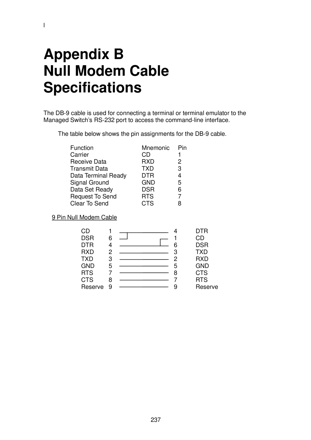
9 Pin Null Modem Cable
CD 1
DSR 6
DTR 4
RXD 2
TXD 3
GND 5
RTS 7
CTS 8
Reserve 9
Mnemonic | Pin | |||
CD | 1 | |||
RXD | 2 | |||
TXD | 3 | |||
DTR | 4 | |||
GND | 5 | |||
DSR | 6 | |||
RTS | 7 | |||
CTS | 8 | |||
4 | DTR | |||
|
|
| 1 | CD |
|
| 6 | DSR | |
| ||||
3 | TXD | |||
2 | RXD | |||
5 | GND | |||
8 | CTS | |||
7 | RTS | |||
9 | Reserve | |||
237