Installation
Lexicon
The Rear Panel
CAUTION: Never make or break any connections to the
5 | 6 | 7 | 8 |
| 4 |
TRIGGERS | TRIGGERS |
| |
| IR IN |
PGM GND PWR | GND |
PWR PGM |
9 | 10 | 11 |
![]() AUDIOS-VIDEO VIDEO
AUDIOS-VIDEO VIDEO
TAPE | TUNER | CD | AUX | TV | DVD | VCR | |
| L |
|
| L |
|
| L |
| R |
|
| R |
|
| R |
|
|
|
| INPUT |
|
|
|
MONITOR
ZONE 2
RECORD 1 RECORD 2
L
R
OUTPUT
![]()
![]()
![]() MAIN OUTPUTS S/PDIF INTPUTS
MAIN OUTPUTS S/PDIF INTPUTS
| S/PDIF OUT |
|
|
|
|
1 | 2 |
|
|
| CAUTION |
B | C |
| RISK OF ELECTRIC SHOCK | ||
| A |
| DO NOT OPEN | ||
| EXPANSION PORTS |
| RS 232 | ATTENTION | |
|
|
|
| RISQUE DE CHOC |
3 | 4 | 5 |
| ELECTRIQUE |
| NE PAS OUVRIR | |||
|
| 1 | 2 | 3 |
REAR | SIDE | CENTER FRONT |
| LISTED AUDIO |
|
|
| 7D77 | LEXICON, INC. |
| |||
|
|
| C | EQUIPMENT | ASSEMBLED IN U.S.A. | |
|
|
| E172268 | |||
|
|
|
|
| ||
| L |
|
| TRIGGERS | TRIGGERS | S |
|
|
|
|
|
| |
|
|
|
|
| IR IN |
|
| R |
|
|
|
|
|
|
| SUBWOOFER |
|
| GND |
|
|
| PGM GND PWR | PWR PGM | |||
|
|
|
|
|
| |
1
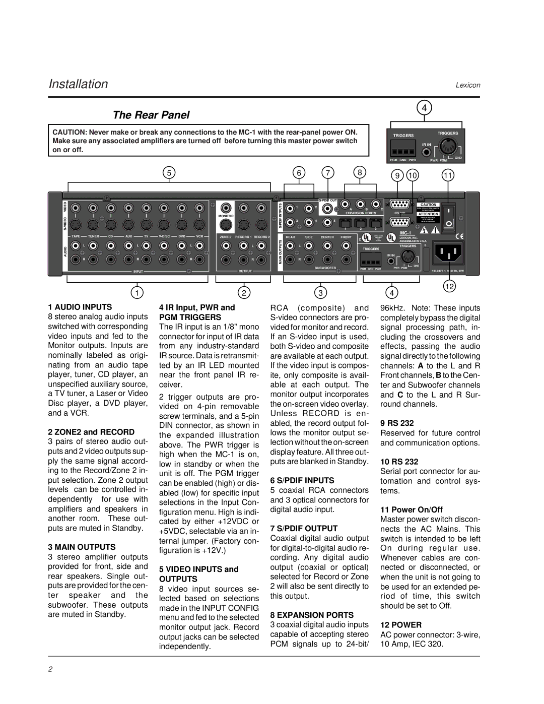
1 AUDIO INPUTS
8 stereo analog audio inputs switched with corresponding video inputs and fed to the Monitor outputs. Inputs are nominally labeled as origi- nating from an audio tape player, tuner, CD player, an unspecified auxiliary source, a TV tuner, a Laser or Video Disc player, a DVD player, and a VCR.
2 ZONE2 and RECORD
3 pairs of stereo audio out- puts and 2 video outputs sup- ply the same signal accord- ing to the Record/Zone 2 in- put selection. Zone 2 output levels can be controlled in- dependently for use with amplifiers and speakers in another room. These out- puts are muted in Standby.
3 MAIN OUTPUTS
3 stereo amplifier outputs provided for front, side and rear speakers. Single out- puts are provided for the cen- ter speaker and the subwoofer. These outputs are muted in Standby.
2
4 IR Input, PWR and
PGM TRIGGERS
The IR input is an 1/8" mono connector for input of IR data from any
2trigger outputs are pro- vided on
5 VIDEO INPUTS and
OUTPUTS
8video input sources se- lected based on selections made in the INPUT CONFIG menu and fed to the selected monitor output jack. Record output jacks can be selected independently.
3
RCA (composite) and
6 S/PDIF INPUTS
5 coaxial RCA connectors and 3 optical connectors for digital audio input.
7 S/PDIF OUTPUT
Coaxial digital audio output for
8 EXPANSION PORTS
3 coaxial digital audio inputs capable of accepting stereo PCM signals up to
12
4
96kHz. Note: These inputs completely bypass the digital signal processing path, in- cluding the crossovers and effects, passing the audio signal directly to the following channels: A to the L and R Front channels, B to the Cen- ter and Subwoofer channels and C to the L and R Sur- round channels.
9 RS 232
Reserved for future control and communication options.
10 RS 232
Serial port connector for au- tomation and control sys- tems.
11 Power On/Off
Master power switch discon- nects the AC Mains. This switch is intended to be left On during regular use. Whenever cables are con- nected or disconnected, or when the unit is not going to be used for an extended pe- riod of time, this switch should be set to Off.
12 POWER
AC power connector:
2