For Example:
395CAV FURNACE | FREE AREA PER OPENING | ROUND PIPE |
INPUT BTUH | (SQ IN.) | (IN. DIA) |
44,000 | 11.0 | 4 |
66,000 | 16.5 | 5 |
88,000 | 22.0 | 6 |
110,000 | 27.5 | 6 |
132,000 | 33.0 | 7 |
154,000 | 38.5 | 7 |
|
|
|
For Example:
395CAV FURNACE | FREE AREA PER OPENING | ROUND PIPE |
INPUT BTUH | (SQ IN.) | (IN. DIA) |
44,000 | 22.0 | 6 |
66,000 | 33.0 | 7 |
88,000 | 44.0 | 8 |
110,000 | 55.0 | 9 |
132,000 | 66.0 | 10 |
154,000 | 77.0 | 10 |
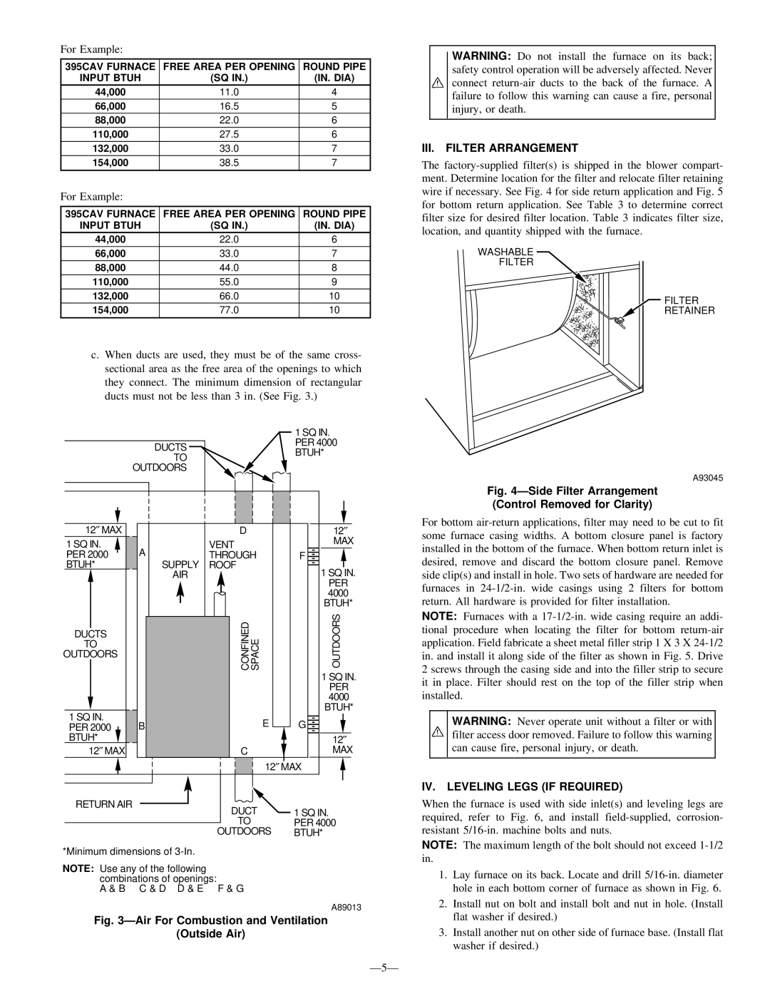
c.When ducts are used, they must be of the same cross- sectional area as the free area of the openings to which they connect. The minimum dimension of rectangular ducts must not be less than 3 in. (See Fig. 3.)
|
|
|
| 1 SQ IN. |
| DUCTS |
|
| PER 4000 |
|
|
| BTUH* | |
| TO |
|
| |
|
|
|
| |
| OUTDOORS |
|
|
|
12″ MAX |
| D |
| 12″ |
1 SQ IN. |
| VENT |
| MAX |
A |
|
| ||
PER 2000 | THROUGH | F | ||
BTUH* | SUPPLY | ROOF |
| 1 SQ IN. |
| AIR |
|
| |
|
|
|
| PER |
|
|
|
| 4000 |
|
|
|
| BTUH* |
DUCTS |
| CONFINED | SPACE | OUTDOORS |
TO |
| |||
OUTDOORS |
| |||
|
| |||
|
|
|
| 1 SQ IN. |
|
|
|
| PER |
|
|
|
| 4000 |
1 SQ IN. |
|
|
| BTUH* |
B |
| E | G | |
PER 2000 |
| |||
BTUH* |
|
|
| 12″ |
″ |
| C |
| MAX |
12 MAX |
|
|
| |
|
|
| 12″ MAX | |
RETURN AIR | DUCT | 1 SQ IN. | ||
|
| |||
|
| TO |
| PER 4000 |
|
| OUTDOORS | BTUH* | |
*Minimum dimensions of
NOTE: Use any of the following combinations of openings:
A & B C & D D & E F & G
A89013
Fig. 3ÐAir For Combustion and Ventilation
(Outside Air)
Ð5Ð
WARNING: Do not install the furnace on its back; safety control operation will be adversely affected. Never connect
III.FILTER ARRANGEMENT
The
WASHABLE
FILTER
FILTER
RETAINER
A93045
Fig. 4ÐSide Filter Arrangement (Control Removed for Clarity)
For bottom
NOTE: Furnaces with a
WARNING: Never operate unit without a filter or with filter access door removed. Failure to follow this warning can cause fire, personal injury, or death.
IV. LEVELING LEGS (IF REQUIRED)
When the furnace is used with side inlet(s) and leveling legs are required, refer to Fig. 6, and install
NOTE: The maximum length of the bolt should not exceed
1.Lay furnace on its back. Locate and drill
2.Install nut on bolt and install bolt and nut in hole. (Install flat washer if desired.)
3.Install another nut on other side of furnace base. (Install flat washer if desired.)