INSTALL
3″ |
24 1/2″ |
1″ |
5⁄16″
13⁄4″
5⁄16″
5⁄16″
1 3⁄4″
5⁄16″
1 3⁄4″ ![]()
![]()
![]() 1 3⁄4″
1 3⁄4″![]()
WASHABLE
FILTER
| FILTER | FILTER |
|
|
| |
| RETAINER |
| ||||
| SUPPORT |
|
|
|
|
|
|
|
|
|
|
| A96030 |
Fig. 5ÐBottom Filter Arrangement |
| |||||
(Control Removed for Clarity) |
| |||||
TABLE 3ÐFILTER INFORMATION (IN.) |
| |||||
|
|
|
|
|
|
|
FURNACE | FILTER SIZE* |
|
|
| FILTER TYPE | |
CASING WIDTH | Side Return | Bottom Return |
| |||
|
| |||||
|
|
|
|
|
| |
(1) 16 X 25 X 1² | (1) 14 | X 25 X 1 |
| Cleanable | ||
(1) 16 X 25 X 1² | (1) 16 | X 25 | X 1 |
| Cleanable | |
21 | (1) 16 X 25 X 1 | (1) 20 | X 25 | X 1² |
| Cleanable |
(2) 16 X 25 X 1² | (1) 24 | X 25 | X 1 |
| Cleanable | |
|
|
|
|
|
|
|
*Filters can be field modified by cutting the frame as marked and folding to the desired size. Alternate sizes can be ordered from your distributor or dealer. ²
4.Adjust outside nut to provide desired height, and tighten inside nut to secure arrangement.
V.GAS PIPING
Gas piping must be installed in accordance with national and local codes. Refer to the current edition of the NFGC. Canadian installations must be installed in accordance with NSCNGPIC and all authorities having jurisdiction.
Refer to Table 4 for the recommended gas pipe size. Risers must be used to connect to the furnace and the meter.
Ð6Ð
|
|
|
|
|
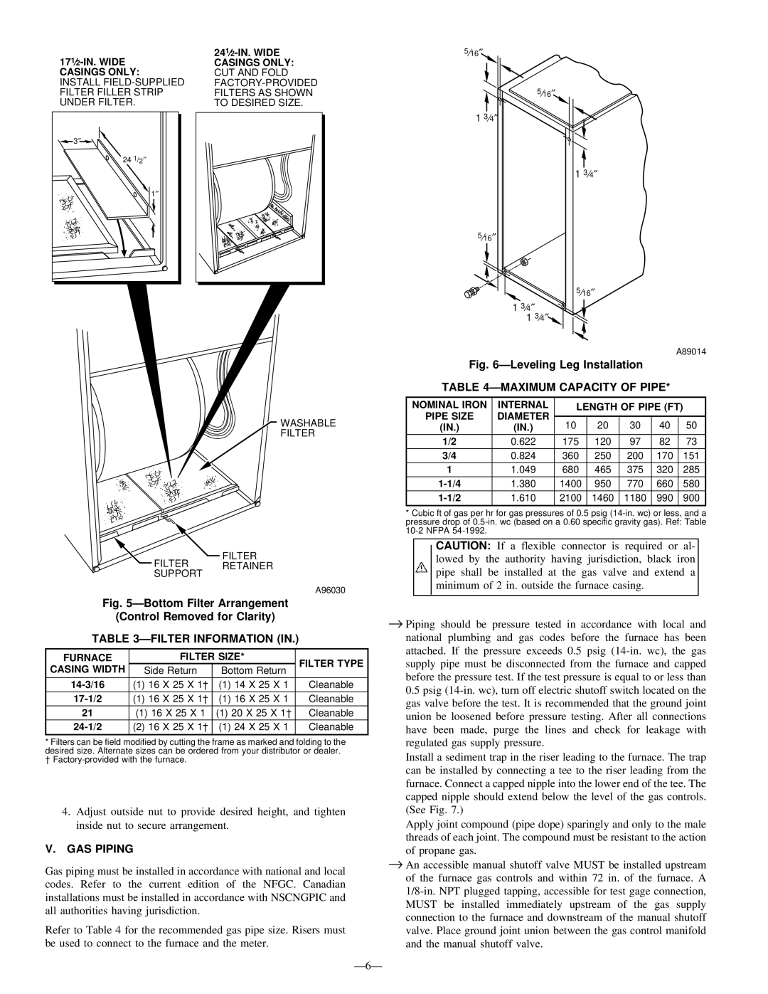
| A89014 | |
Fig. 6ÐLeveling Leg Installation |
|
|
| ||||
TABLE 4ÐMAXIMUM CAPACITY OF PIPE* |
|
| |||||
|
|
|
|
|
|
| |
NOMINAL IRON | INTERNAL | LENGTH OF PIPE (FT) | |||||
PIPE SIZE | DIAMETER |
|
|
|
|
|
|
10 | 20 | 30 | 40 |
| 50 | ||
(IN.) | (IN.) |
| |||||
1/2 | 0.622 | 175 | 120 | 97 | 82 |
| 73 |
3/4 | 0.824 | 360 | 250 | 200 | 170 |
| 151 |
1 | 1.049 | 680 | 465 | 375 | 320 |
| 285 |
1.380 | 1400 | 950 | 770 | 660 |
| 580 | |
1.610 | 2100 | 1460 | 1180 | 990 |
| 900 | |
*Cubic ft of gas per hr for gas pressures of 0.5 psig
CAUTION: If a flexible connector is required or al- lowed by the authority having jurisdiction, black iron pipe shall be installed at the gas valve and extend a minimum of 2 in. outside the furnace casing.
→Piping should be pressure tested in accordance with local and national plumbing and gas codes before the furnace has been attached. If the pressure exceeds 0.5 psig
Install a sediment trap in the riser leading to the furnace. The trap can be installed by connecting a tee to the riser leading from the furnace. Connect a capped nipple into the lower end of the tee. The capped nipple should extend below the level of the gas controls. (See Fig. 7.)
Apply joint compound (pipe dope) sparingly and only to the male threads of each joint. The compound must be resistant to the action of propane gas.
→An accessible manual shutoff valve MUST be installed upstream of the furnace gas controls and within 72 in. of the furnace. A