Plasma TV
LG Electronics U.S.A., Inc
Power Cord Polarization
TV Guide On Screen Notices for U.S.A
Important safeguards for you and your new product
Cleaning
Accessories, Carts, and Stands
Power Sources
Safety Instructions
Contents
What is a Plasma Display Panel PDP?
How does it work?
Wide angle range of vision
Wide Screen
Controls
Connection Options
Thumbstick Up/Down/Left/Right/ENTER
Remote Control Key Functions
Number buttons
Installation
Installation Instructions
Grounding
Analog and Digital TV signals provided on antenna
Analog and Digital TV signals provided on cable
External Equipment Connections
Antenna or Cable Connection
Connection Option
Analog and Digital TV signals provided on cable and antenna
VCR Setup
External A/V Source Setup
How to connect
How to use
Component Input ports
Digital Set-top Box
CableCARDTM Setup
Hdstb Setup
Resolution Horizontal Vertical
PC Setup
Monitor Display Specifications RGB-PC
Digital Audio Output
Monitor Display Specifications HDMI/DVI Mode
Monitor Out Setup
HDMI/DVI Video
Reference
This Mode, the Supported TV SET Resolution Specification
This Mode, the Supported PC Resolution Specification
Cable Service without a Cable Box
How to connect VCR and Cable Box
Antenna Service
Antenna and Cable Service with a Cable Box
Cable Service with a Cable Box
Antenna and Cable Service without a Cable Box
Welcome Screen
How to use Screen 1 Country
Reminder Screen
Screen 4 Do you have a Cable Box?
Screen 2 Enter Zip or Postal Code Option
Screen 3 Do you have Cable?
Screen 6 Cable Box Tuning Channel
Screen 7 Cable Box Configuration Diagram
Make sure the G-LINK Cable is properly installed
Screen 5 Which TV input is the cable box plugged into?
Screen 10 Cable Box Code Testing
Screen 8 Cable Box Brand Name
Screen 9 Cable Box Preparation
Screen 11 Cable Box Tuned to Channel 9?
Screen 14 Congratulations
Screen 13 Are your basic settings correct?
Screen 12 Do you have an antenna connected?
Screen 17 VCR Brand Name
Screen 16 VCR Configuration Diagram
Screen 15 Is a VCR Connected?
Screen 20 VCR Tuned to Channel 9?
Screen 19 VCR Code Testing
Screen 18 VCR Preparation
Screen 23 Helpful Information
Screen 21 Confirming Your Settings
Screen 22 Congratulations
Ieee 1394 Functions
To work the 1394, this 3 methods can used
VHow to play the Dvhs
How to play the MicroMV Camcorder
MicroMV Camcorder
How to play the MicroMV Camcorder and Dvhs
MicroMV Camcorder and Dvhs
Loop Connection Daisy Chain Connect the IEEE1394 Cable
TV Guide On Screen System
TV Guide On Screen Overview
TV Guide On Screen System
Panel Menu
Main Services
Listings
Search
Category Search Example Movies
TV Guide On Screen System
Keyword Search
TV Guide On Screen System
Record
Remind
Setup
Change System Settings
Change Channel Display
Change Default Options
TV Guide On Screen System
Record And Remind Features
Using the Record Button on the Remote
Cancel no icon displayed-does not record
From a Panel Menu
Manual Recording
Record Conflict
Remind
Manual Reminder
Remind Conflict
Initializing Reset to original factory values
Screen Setup for PC mode
Adjustment for screen Position, Size, and Phase
Turning the TV On
On-screen Menus Language Selection
Manual Scan
Setup Menu Options
EZ Scan Channel Search
DTV Signal Strength
Channel Edit
Aux. Label
Channel Label Setup
Main Picture Source Selection
Color Temperature Control
Video Menu Options
EZ Picture
Manual Picture Control Off option
Video Preset
Audio Menu Options
Audio Language
EZ SoundRite
EZ Sound
Front Surround
TV Speakers On/Off Setup
Stereo/SAP Broadcasts Setup
Auto Clock Setup
Manual Clock Setup
On/Off Timer Setup
For only On timer function
Sleep Timer
Auto Off
Aspect Ratio Control
Option Menu Features
Cinema Mode Setup
Caption
Caption/Text
Analog Broadcasting System Captions
Digital Broadcasting System Captions
Caption Option
Demo
ISM Image Sticking Minimization Method
Low Power
Split Zoom DTV 720p, or 1080i mode only
Lock Menu Options
Chip rating and categories
TV Rating Children
TV Rating General
Parental Lock Setup
Scrambled channel
CableCARD Function
Cable menu options
Cable Channel List
Emergency Alert Message
Remote Control
Selecting an Input Signal Source for PIP/Twin Picture
Watching PIP/POP/Twin Picture
Swapping the PIP/Twin Picture
POP Picture-out-of-Picture Channel Scan
Adjusting Main and Sub Picture Sizes for Twin Picture
Moving the PIP sub picture
Information
EZ Mute
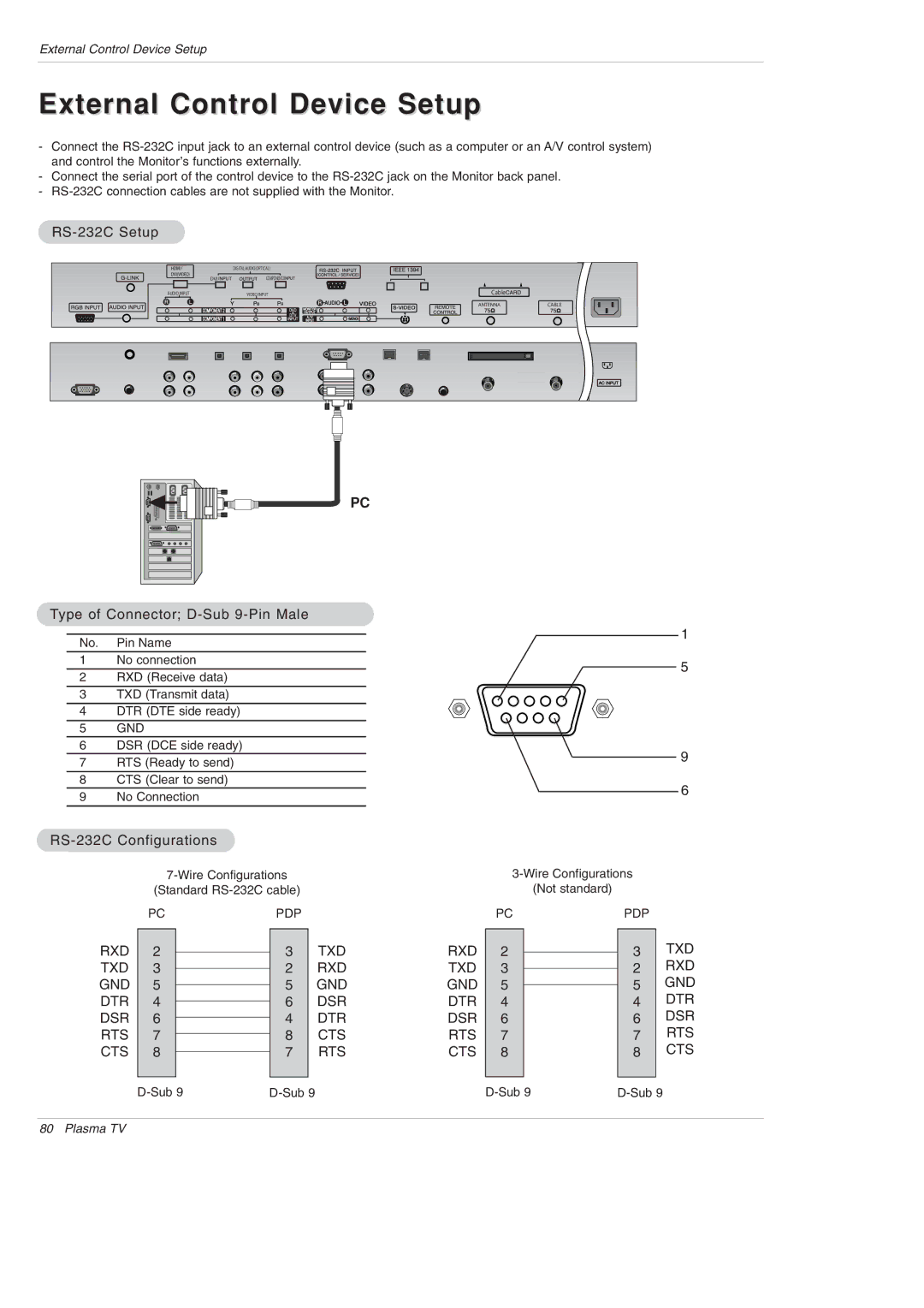
External Control Device Setup
RS-232C Setup
Type of Connector D-Sub 9-Pin Male
RS-232C Configurations
Command Reference List
Set ID
Communication Parameters
Transmission / Receiving Protocol
Power Command2a
Volume Mute Command2e
Input Select Command2b Main Picture Input
Aspect Ratio Command2c Main picture format
Color Command2i
Tint Command2j
Sharpness Command2k
OSD Select Command2l
Color Temperature Command2u
PIP Input Select Command2y
ISM Method Command2p
White Wash Command2q
How to Connect
Remote Control IR Codes
Code Hexa Function
Programming a code into a remote mode
Programming the Remote
Programming Codes
VCRs
Hdstb
Audio
Troubleshooting Checklist
Extended Absence
Cleaning the Screen
Cleaning the Cabinet
Product Specifications
DU-42PY10X
Page
Plasma TV
LG ELECTRONICS, INC Plasma TV U.S. Limited Warranty
This Limited Warranty does not Apply to
No 3828VA0479E 3828VB0002L