ITR specifications
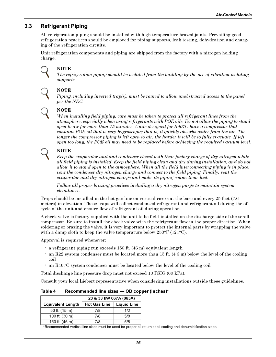
The Liebert ITR is an advanced precision cooling unit designed to maintain optimal temperature and humidity levels in mission-critical environments. Engineered for high-performance applications, it is particularly suitable for data centers, telecommunications facilities, and other spaces that require precise climate control to ensure uninterrupted operation of sensitive equipment.One of the main features of the Liebert ITR is its modular design. This allows for scalability and flexibility, enabling users to customize the system based on their specific cooling needs. The unit can be configured in various sizes and cooling capacities, making it suitable for both small server rooms and large data centers. This adaptability is crucial for organizations that anticipate growth and require an efficient cooling solution that can evolve with their infrastructure.
The Liebert ITR incorporates state-of-the-art technologies to enhance performance and energy efficiency. Among these technologies is the use of a variable speed compressor that adjusts its speed based on the cooling load. This capability not only improves energy efficiency but also significantly reduces operational costs by minimizing electricity consumption when cooling demands fluctuate.
Additionally, the unit features advanced control systems that provide intelligent monitoring and management of temperature and humidity levels. These systems can integrate seamlessly with building management systems (BMS) and can be operated remotely, providing users with real-time insights into the performance of the cooling system. Such connectivity ensures quick identification and resolution of potential issues, thereby reducing downtime and maintaining optimal conditions for critical equipment.
The Liebert ITR utilizes eco-friendly refrigerants, contributing to reduced environmental impact while ensuring compliance with regulatory standards. The unit's design also emphasizes reliability, featuring robust construction and redundant components that enhance longevity and minimize the likelihood of failures.
Furthermore, the Liebert ITR is equipped with advanced filtration systems that maintain air quality by reducing particulate matter and contaminants, ensuring that the atmosphere within data centers is not only cool but also clean—critical for the longevity of sensitive electronic equipment.
Overall, the Liebert ITR is characterized by its innovative design, energy-efficient operation, and comprehensive control capabilities, making it an ideal choice for businesses looking to safeguard their critical infrastructure from overheating and humidity. As climate control becomes increasingly important in the digital age, the Liebert ITR stands out as a reliable solution for maintaining optimal environmental conditions.

