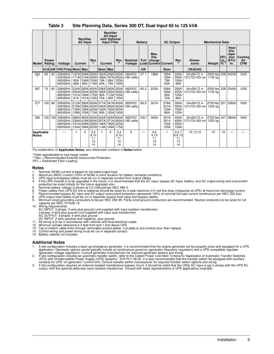
| Table 3 | Site Planning Data, Series 300 DT, Dual Input 65 to 125 kVA |
|
|
|
|
| |||||||||||||
|
|
|
|
|
|
|
|
|
|
|
|
|
|
|
|
|
|
|
|
|
|
|
|
|
|
|
| Rectifier |
|
|
|
|
|
|
|
|
|
|
| ||
|
|
|
| Rectifier | AC Input |
|
|
|
|
|
|
|
|
|
|
| ||||
|
|
|
| with Optional |
|
|
|
|
|
|
|
|
|
|
| |||||
|
|
|
| AC Input | Input Filter | Battery |
| AC Output |
| Mechanical Data |
| |||||||||
|
|
|
|
|
|
|
|
|
|
|
|
|
|
|
|
|
|
| Heat |
|
|
|
|
|
|
|
|
|
|
|
|
|
|
|
|
|
|
|
| Dis- |
|
|
|
|
|
|
|
|
|
|
|
|
| Max. |
|
|
|
|
|
| sipa- |
|
|
|
|
|
|
|
|
|
|
|
|
| Dis- |
|
|
|
|
| DFL | tion | Cooling |
| Power |
|
|
| Rec |
|
| Rec | Nominal | Full | charge |
| Rec | Dimen- |
|
| Lb./ | BTU/ | Air | |
Model | Rating | Voltage | Current | ** | Current | ** | Voltage | Load | Current | Current | ** | sions |
| Weight | Ft.2 | hr. | CFM | |||
| kVA | kW | VAC/Freq | Nom | Max |
| Nom | Max |
|
| kW |
| Nom |
| (WxDxH) |
|
|
|
|
|
362 | 65 | 52 | 208/60Hz | 197A | 246A | 300A | 182A | 228A | 300A | 360VDC | 57.1 | 198A | 180A | 225A | 54x28x72 in |
| 2500 lbs | 238 | 24200 | 1200 |
* |
|
| 240/60Hz | 171A | 214A | 300A | 158A | 197A | 250A | (180 cells) |
|
| 155A | 200A | 137x72x183 cm | 1134 kg |
|
|
| |
|
|
| 480/60Hz | 85A | 106A | 150A | 79A | 99A | 125A |
|
|
| 78A | 100A |
|
|
|
|
|
|
|
|
| 600/60Hz | 68A | 85A | 110A | 63A | 79A | 100A |
|
|
| 63A | 80A |
|
|
|
|
|
|
|
|
|
|
|
|
|
|
|
|
|
|
|
|
|
|
|
|
|
|
|
367 | 75 | 60 | 208/60Hz | 234A | 293A | 400A | 208A | 260A | 350A | 360VDC | 65.2 | 225A | 208A | 300A | 54x28x72 in |
| 2500 lbs | 238 | 25400 | 1200 |
|
|
| 240/60Hz | 203A | 254A | 350A | 180A | 225A | 300A | (180 cells) |
|
| 180A | 225A | 137x72x183 cm | 1134 kg |
|
|
| |
|
|
| 480/60Hz | 101A | 126A | 175A | 90A | 113A | 150A |
|
|
| 90A | 125A |
|
|
|
|
|
|
|
|
| 600/60Hz | 81A | 101A | 125A | 72A | 90A | 125A |
|
|
| 72A | 90A |
|
|
|
|
|
|
|
|
|
|
|
|
|
|
|
|
|
|
|
|
|
|
|
|
|
|
|
377 | 100 | 80 | 208/60Hz | 312A | 390A | 500A | 277A | 347A | 450A | 360VDC | 86.5 | 307A | 278A | 350A | 54x28x72 in |
| 2700 lbs | 257 | 33800 | 1600 |
* |
|
| 240/60Hz | 270A | 338A | 450A | 240A | 300A | 400A | (180 cells) |
|
| 241A | 300A | 137x72x183 cm | 1225 kg |
|
|
| |
|
|
| 480/60Hz | 135A | 169A | 225A | 120A | 150A | 200A |
|
|
| 120A | 150A |
|
|
|
|
|
|
|
|
| 600/60Hz | 108A | 135A | 175A | 95A | 120A | 150A |
|
|
| 96A | 125A |
|
|
|
|
|
|
|
|
|
|
|
|
|
|
|
|
|
|
|
|
|
|
|
|
|
|
|
382 | 125 | 100 | 208/60Hz | 386A | 483A | 600A | 343A | 429A | 600A | 360VDC | 108.1 | 383A | 347A | 450A | 54x28x72 in |
| 2700 lbs | 257 | 38000 | 1600 |
|
|
| 240/60Hz | 334A | 418A | 600A | 297A | 371A | 450A | (180 cells) |
|
| 301A | 400A | 137x72x183 cm | 1225 kg |
|
|
| |
|
|
| 480/60Hz | 167A | 209A | 300A | 148A | 185A | 225A |
|
|
| 150A | 200A |
|
|
|
|
|
|
|
|
| 600/60Hz | 134A | 168A | 225A | 119A | 149A | 175A |
|
|
| 120A | 150A |
|
|
|
|
|
|
|
|
|
|
|
|
|
|
|
|
|
|
|
|
|
|
|
|
|
|
|
Applicable |
| — | 1 | 2 | 3,4 | 1 | 2 | 3,4 | 5 | — | 4,6 | 1 | 3,4,7 | 12,13,15 |
| 15 | 15 | — | — | |
Notes: |
|
|
|
|
| 9,10 |
|
| 9,10 |
|
| 9,10 |
| 8,9,10 |
|
|
|
|
|
|
|
|
|
|
|
| 11 |
|
| 11 |
|
| 11 |
| 11 |
|
|
|
|
|
|
|
|
|
|
|
| 13 |
|
| 13 |
|
| 13 |
| 13 |
|
|
|
|
|
|
|
|
|
|
|
| 14 |
|
| 14 |
|
| 14 |
| 14 |
|
|
|
|
|
|
|
|
|
|
|
|
|
|
|
|
|
|
|
|
|
|
|
|
|
|
|
For explanation of Applicable Notes, see referenced numbers in Notes below.
**Rec = Recommended External Overcurrent Protection DFL = Distributed Floor Loading
Notes
1.Nominal (NOM) current is based on full rated output load.
2.Maximum (MAX) current (125% of NOM) is short duration for battery recharge conditions.
3.UPS input and bypass cables must be run in separate conduit from output cables.
4.If the UPS module is to be upgraded in the future, it is recommended that the AC input, bypass AC input, battery, and AC output wiring and overcurrent protection be sized initially for the future upgraded size.
5.Nominal battery voltage is shown at 2.0 volts/cell per NEC
6.Power cables from UPS DC link to batteries should be sized for a total maximum 2.0 volt line drop (measured at UPS) at maximum discharge current.
7.Recommended bypass AC input and AC output overcurrent protection represents 125% of nominal full load current (continuous) per NEC
8.UPS output load cables must be run in separate conduit from input and bypass cables.
9.Minimum sized grounding conductors to be per NEC
10.Wiring requirements:
AC INPUT:
DC INPUT:
11.All wiring is to be in accordance with national and local electrical codes.
12.Minimum access clearance is 3 feet front and 1 foot above UPS.
13.Top or bottom cable entry through removable access plates. Cut plate to suit conduit size, then replace.
14.Control wiring and power wiring must be run in separate conduit.
15.Battery cabinet not included.
Additional Notes
1.If site configuration includes a
2.If site configuration includes an automatic transfer switch, refer to the Liebert Power Line titled “Criteria for Application of Automatic Transfer Switches (ATS) with Uninterruptible Power Supply (UPS) Systems.”
3.If site configuration requires an external isolated maintenance bypass circuit, it should be noted that the Utility AC input is not in phase with the UPS AC output, with the optional
Installation 9