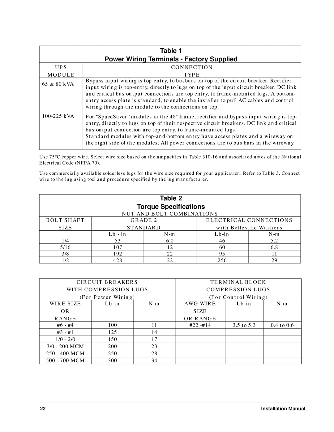
| Table 1 | |
| Power Wiring Terminals - Factory Supplied | |
UPS | CONNECTION | |
MODULE | TYPE | |
65 & 80 kVA | Bypass input wiring is | |
input wiring is | ||
| ||
| and critical bus output connections are top entry, to | |
| entry access plate is standard, to enable the installer to pull AC cables and control | |
| wiring through the module to the connections on top. | |
For “SpaceSaver” modules in the 48” frame, rectifier and bypass input wiring is top- | ||
| entry, directly to lugs on top of their respective circuit breakers. DC link and critical | |
| bus output connection are top entry, to | |
| Standard modules with | |
| the right side of the modules. All power connections are to bus bars in the wireway. | |
|
|
Use 75°C copper wire. Select wire size based on the ampacities in Table
Use commercially available solderless lugs for the wire size required for your application. Refer to Table 3. Connect wire to the lug using tool and procedure specified by the lug manufacturer.
Table 2
Torque Specifications
| NUT AND BOLT COMBINATIONS |
|
|
|
| |||||||
BOLT SHAFT | GRADE 2 |
| ELECTRICAL CONNECTIONS | |||||||||
SIZE | STANDARD |
| with Belleville Washers | |||||||||
| Lb - in |
|
|
|
|
| ||||||
1/4 | 53 |
|
| 6.0 |
|
| 46 |
|
|
|
| 5.2 |
5/16 | 107 |
|
| 12 |
|
| 60 |
|
|
|
| 6.8 |
3/8 | 192 |
|
| 22 |
|
| 95 |
|
|
|
| 11 |
1/2 | 428 |
|
| 22 |
|
| 256 |
|
|
| 29 | |
|
|
|
|
|
|
|
|
| ||||
CIRCUIT BREAKERS |
|
|
| TERMINAL BLOCK |
| |||||||
WITH COMPRESSION LUGS |
|
|
| COMPRESSION LUGS | ||||||||
(For Power Wiring) |
|
|
| (For Control Wiring) |
| |||||||
WIRE SIZE |
|
|
| AWG WIRE |
|
| ||||||
OR |
|
|
|
|
| SIZE |
|
|
|
|
| |
RANGE |
|
|
|
|
| OR RANGE |
|
|
|
|
| |
#6 - #4 | 100 |
|
| 11 |
| #22 |
| 3.5 to 5.3 |
| 0.4 to 0.6 | ||
#3 - #1 | 125 |
|
| 14 |
|
|
|
|
|
|
|
|
1/0 - 2/0 | 150 |
|
| 17 |
|
|
|
|
|
|
|
|
3/0 - 200 MCM | 200 |
|
| 23 |
|
|
|
|
|
|
|
|
250 - 400 MCM | 250 |
|
| 28 |
|
|
|
|
|
|
|
|
500 - 700 MCM | 300 |
|
| 34 |
|
|
|
|
|
|
|
|
22 | Installation Manual |