4.0OPERATOR CONTROLS
4.1Bypass/Transfer Control Switch
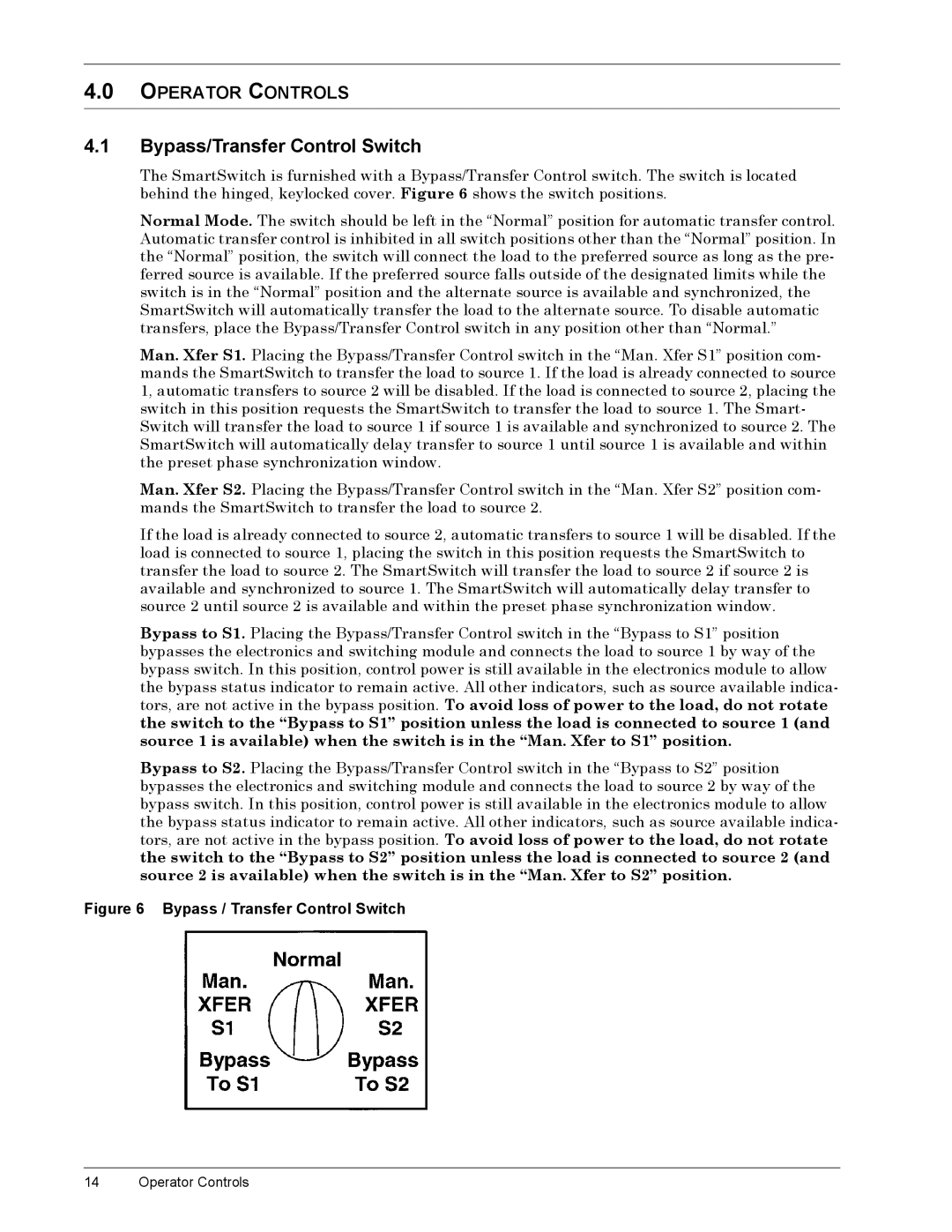
The SmartSwitch is furnished with a Bypass/Transfer Control switch. The switch is located behind the hinged, keylocked cover. Figure 6 shows the switch positions.
Normal Mode. The switch should be left in the “Normal” position for automatic transfer control. Automatic transfer control is inhibited in all switch positions other than the “Normal” position. In the “Normal” position, the switch will connect the load to the preferred source as long as the pre- ferred source is available. If the preferred source falls outside of the designated limits while the switch is in the “Normal” position and the alternate source is available and synchronized, the SmartSwitch will automatically transfer the load to the alternate source. To disable automatic transfers, place the Bypass/Transfer Control switch in any position other than “Normal.”
Man. Xfer S1. Placing the Bypass/Transfer Control switch in the “Man. Xfer S1” position com- mands the SmartSwitch to transfer the load to source 1. If the load is already connected to source 1, automatic transfers to source 2 will be disabled. If the load is connected to source 2, placing the switch in this position requests the SmartSwitch to transfer the load to source 1. The Smart- Switch will transfer the load to source 1 if source 1 is available and synchronized to source 2. The SmartSwitch will automatically delay transfer to source 1 until source 1 is available and within the preset phase synchronization window.
Man. Xfer S2. Placing the Bypass/Transfer Control switch in the “Man. Xfer S2” position com- mands the SmartSwitch to transfer the load to source 2.
If the load is already connected to source 2, automatic transfers to source 1 will be disabled. If the load is connected to source 1, placing the switch in this position requests the SmartSwitch to transfer the load to source 2. The SmartSwitch will transfer the load to source 2 if source 2 is available and synchronized to source 1. The SmartSwitch will automatically delay transfer to source 2 until source 2 is available and within the preset phase synchronization window.
Bypass to S1. Placing the Bypass/Transfer Control switch in the “Bypass to S1” position bypasses the electronics and switching module and connects the load to source 1 by way of the bypass switch. In this position, control power is still available in the electronics module to allow the bypass status indicator to remain active. All other indicators, such as source available indica- tors, are not active in the bypass position. To avoid loss of power to the load, do not rotate the switch to the “Bypass to S1” position unless the load is connected to source 1 (and source 1 is available) when the switch is in the “Man. Xfer to S1” position.
Bypass to S2. Placing the Bypass/Transfer Control switch in the “Bypass to S2” position bypasses the electronics and switching module and connects the load to source 2 by way of the bypass switch. In this position, control power is still available in the electronics module to allow the bypass status indicator to remain active. All other indicators, such as source available indica- tors, are not active in the bypass position. To avoid loss of power to the load, do not rotate the switch to the “Bypass to S2” position unless the load is connected to source 2 (and source 2 is available) when the switch is in the “Man. Xfer to S2” position.
Figure 6 Bypass / Transfer Control Switch
14 Operator Controls