3.3RS-232 Communications Port
The SmartSwitch contains an
The default parameters of the communications port are
The port uses a
The Event Log contains the last 175 switch events. The Settings Log contains the last 50 switch settings changes.
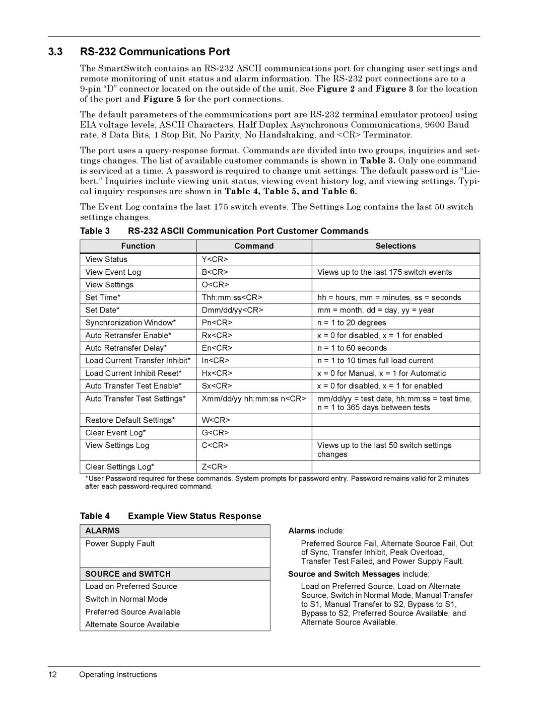
Table 3 |
| ||
|
|
|
|
| Function | Command | Selections |
View Status | Y<CR> |
| |
View Event Log | B<CR> | Views up to the last 175 switch events | |
View Settings | O<CR> |
| |
Set Time* |
| Thh:mm:ss<CR> | hh = hours, mm = minutes, ss = seconds |
Set Date* |
| Dmm/dd/yy<CR> | mm = month, dd = day, yy = year |
|
|
| |
Synchronization Window* | Pn<CR> | n = 1 to 20 degrees | |
Auto Retransfer Enable* | Rx<CR> | x = 0 for disabled, x = 1 for enabled | |
Auto Retransfer Delay* | En<CR> | n = 1 to 60 seconds | |
Load Current Transfer Inhibit* | In<CR> | n = 1 to 10 times full load current | |
|
|
| |
Load Current Inhibit Reset* | Hx<CR> | x = 0 for Manual, x = 1 for Automatic | |
Auto Transfer Test Enable* | Sx<CR> | x = 0 for disabled, x = 1 for enabled | |
Auto Transfer Test Settings* | Xmm/dd/yy hh:mm:ss n<CR> | mm/dd/yy = test date, hh:mm:ss = test time, | |
|
|
| n = 1 to 365 days between tests |
Restore Default Settings* | W<CR> |
| |
Clear Event Log* | G<CR> |
| |
View Settings Log | C<CR> | Views up to the last 50 switch settings | |
|
|
| changes |
Clear Settings Log* | Z<CR> |
| |
|
|
|
|
*User Password required for these commands. System prompts for password entry. Password remains valid for 2 minutes after each
Table 4 Example View Status Response
ALARMS
Power Supply Fault
SOURCE and SWITCH
Load on Preferred Source
Switch in Normal Mode
Preferred Source Available
Alternate Source Available
Alarms include:
Preferred Source Fail, Alternate Source Fail, Out of Sync, Transfer Inhibit, Peak Overload, Transfer Test Failed, and Power Supply Fault.
Source and Switch Messages include:
Load on Preferred Source, Load on Alternate Source, Switch in Normal Mode, Manual Transfer to S1, Manual Transfer to S2, Bypass to S1, Bypass to S2, Preferred Source Available, and Alternate Source Available.
12 Operating Instructions