FIGURE 7 | 35 1/2 X |
3
16
FIGURE 8
3
32 3/8 X
26
17
16
FIGURE 9 |
31 |
49 |
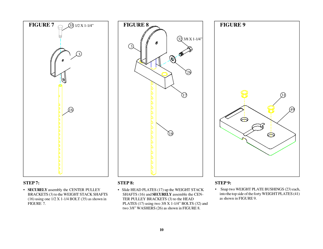
STEP 7:
•SECURELY assembly the CENTER PULLEY BRACKETS (3) to the WEIGHT STACK SHAFTS (16) using one 1/2 X
STEP 8:
•Slide HEAD PLATES (17) up the WEIGHT STACK SHAFTS (16) and SECURELY assemble the CEN- TER PULLEY BRACKETS (3) to the HEAD PLATES (17) using two 3/8 X
STEP 9:
•Snap two WEIGHT PLATE BUSHINGS (23) each, into the top side of the forty WEIGHT PLATES (41) as shown in FIGURE 9.
10
