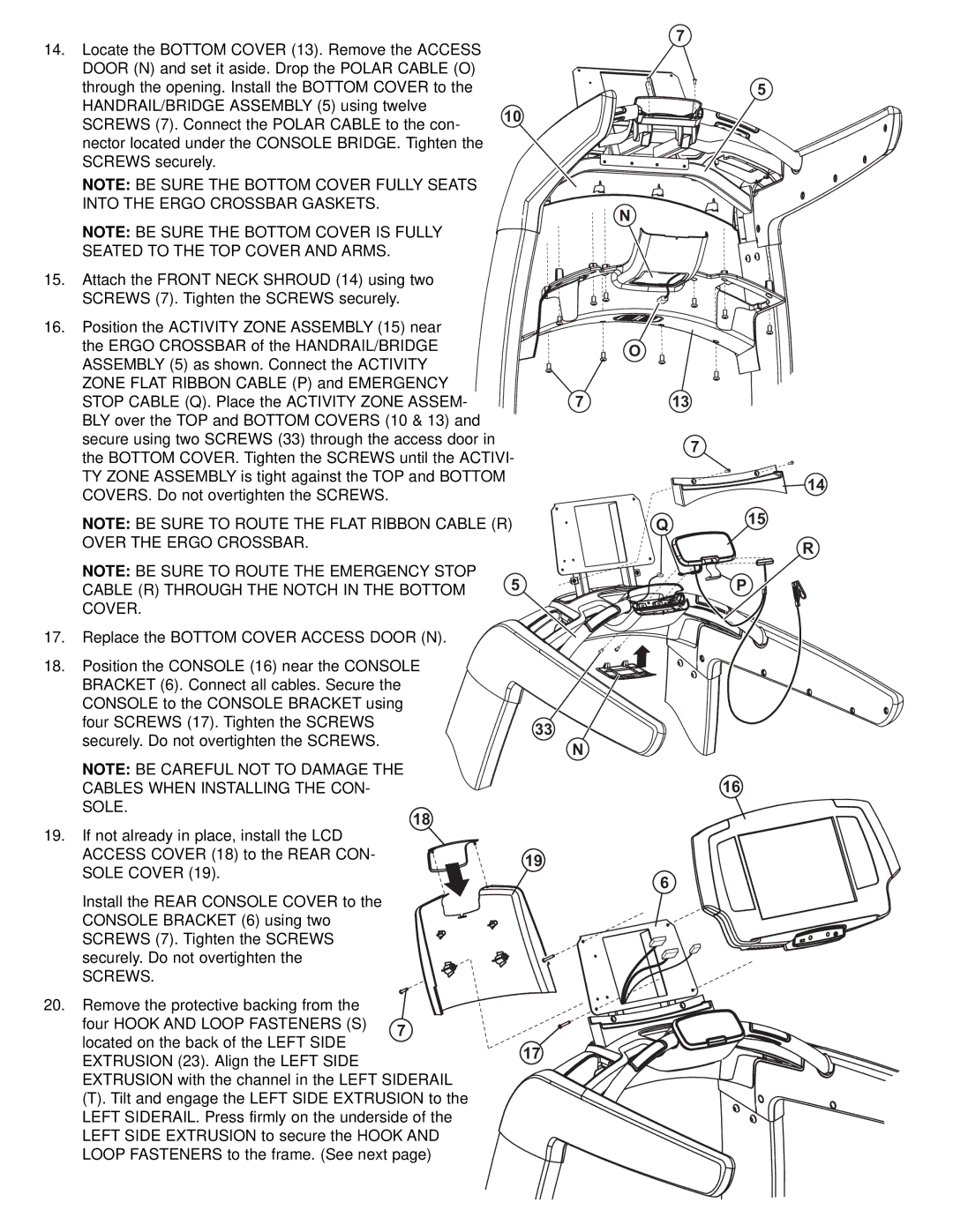
14. Locate the BOTTOM COVER (13). Remove the ACCESS
DOOR (N) and set it aside. Drop the POLAR CABLE (O) |
| |
through the opening. Install the BOTTOM COVER to the |
| |
HANDRAIL/BRIDGE ASSEMBLY (5) using twelve | 10 | |
SCREWS (7). Connect the POLAR CABLE to the con- | ||
| ||
nector located under the CONSOLE BRIDGE. Tighten |
| |
SCREWS securely. |
|
NOTE: BE SURE THE BOTTOM COVER FULLY SEATS INTO THE ERGO CROSSBAR GASKETS.
NOTE: BE SURE THE BOTTOM COVER IS FULLY
SEATED TO THE TOP COVER AND ARMS.
15. Attach the FRONT NECK SHROUD (14) using two |
| |
| SCREWS (7). Tighten the SCREWS securely. |
|
16. Position the ACTIVITY ZONE ASSEMBLY (15) near |
| |
| the ERGO CROSSBAR of the HANDRAIL/BRIDGE |
|
| ASSEMBLY (5) as shown. Connect the ACTIVITY |
|
| ZONE FLAT RIBBON CABLE (P) and EMERGENCY |
|
| STOP CABLE (Q). Place the ACTIVITY ZONE ASSEM- |
|
| BLY over the TOP and BOTTOM COVERS (10 & 13) |
|
| secure using two SCREWS (33) through the access door in |
|
| the BOTTOM COVER. Tighten the SCREWS until the ACTIVI- | |
| TY ZONE ASSEMBLY is tight against the TOP and BOTTOM |
|
| COVERS. Do not overtighten the SCREWS. |
|
| NOTE: BE SURE TO ROUTE THE FLAT RIBBON CABLE (R) | |
| OVER THE ERGO CROSSBAR. |
|
| NOTE: BE SURE TO ROUTE THE EMERGENCY STOP | 5 |
| CABLE (R) THROUGH THE NOTCH IN THE BOTTOM | |
|
| |
| COVER. |
|
17. | Replace the BOTTOM COVER ACCESS DOOR (N). |
|
7 |
5
N
O |
7 | 13 |
7
| 14 |
Q | 15 |
| |
| R |
| P |
18. Position the CONSOLE (16) near the CONSOLE |
| |
BRACKET (6). Connect all cables. Secure the |
| |
CONSOLE to the CONSOLE BRACKET using |
| |
four SCREWS (17). Tighten the SCREWS | 33 | |
securely. Do not overtighten the SCREWS. | ||
N | ||
| ||
NOTE: BE CAREFUL NOT TO DAMAGE THE |
| |
CABLES WHEN INSTALLING THE CON- | 16 | |
SOLE. |
|
18
19.If not already in place, install the LCD
ACCESS COVER (18) to the REAR CON- | 19 |
SOLE COVER (19). | 6 |
|
Install the REAR CONSOLE COVER to the CONSOLE BRACKET (6) using two SCREWS (7). Tighten the SCREWS securely. Do not overtighten the
SCREWS.
20.Remove the protective backing from the
four HOOK AND LOOP FASTENERS (S) | 7 | |
located on the back of the LEFT SIDE | 17 | |
EXTRUSION (23). Align the LEFT SIDE | ||
| ||
EXTRUSION with the channel in the LEFT SIDERAIL | ||
(T). Tilt and engage the LEFT SIDE EXTRUSION to | ||
LEFT SIDERAIL. Press firmly on the underside of the | ||
LEFT SIDE EXTRUSION to secure the HOOK AND | ||
LOOP FASTENERS to the frame. (See next page) | ||