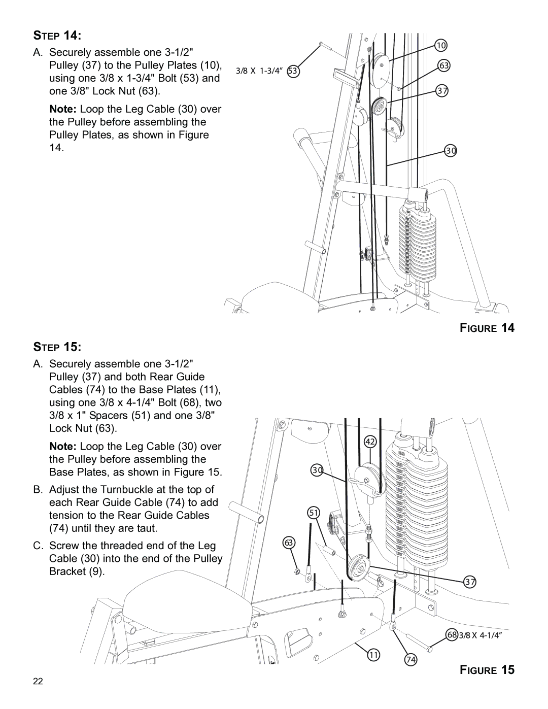
STEP 14:
A.Securely assemble one
Note: Loop the Leg Cable (30) over the Pulley before assembling the Pulley Plates, as shown in Figure 14.
STEP 15:
A.Securely assemble one
Note: Loop the Leg Cable (30) over the Pulley before assembling the Base Plates, as shown in Figure 15.
B.Adjust the Turnbuckle at the top of each Rear Guide Cable (74) to add tension to the Rear Guide Cables
(74)until they are taut.
C.Screw the threaded end of the Leg Cable (30) into the end of the Pulley Bracket (9).
FIGURE 14
FIGURE 15
22