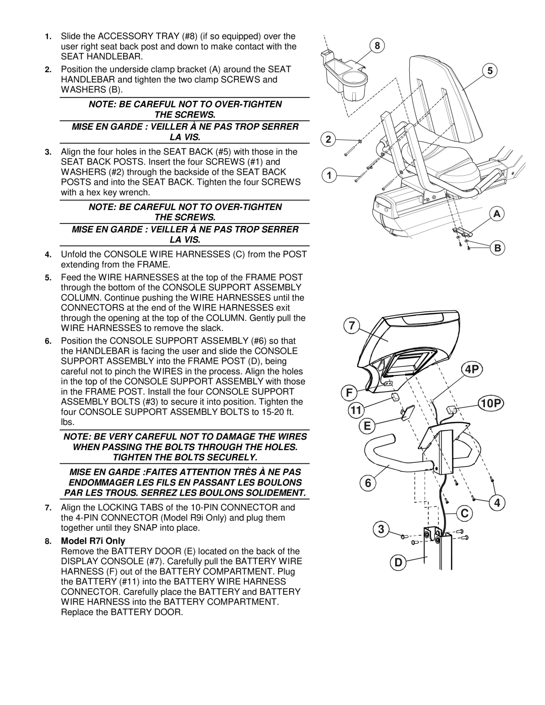
1.Slide the ACCESSORY TRAY (#8) (if so equipped) over the user right seat back post and down to make contact with the
SEAT HANDLEBAR.
2.Position the underside clamp bracket (A) around the SEAT HANDLEBAR and tighten the two clamp SCREWS and WASHERS (B).
NOTE: BE CAREFUL NOT TO
THE SCREWS.
MISE EN GARDE : VEILLER À NE PAS TROP SERRER
LA VIS.
3.Align the four holes in the SEAT BACK (#5) with those in the SEAT BACK POSTS. Insert the four SCREWS (#1) and WASHERS (#2) through the backside of the SEAT BACK POSTS and into the SEAT BACK. Tighten the four SCREWS with a hex key wrench.
NOTE: BE CAREFUL NOT TO
THE SCREWS.
MISE EN GARDE : VEILLER À NE PAS TROP SERRER
LA VIS.
4.Unfold the CONSOLE WIRE HARNESSES (C) from the POST extending from the FRAME.
5.Feed the WIRE HARNESSES at the top of the FRAME POST through the bottom of the CONSOLE SUPPORT ASSEMBLY COLUMN. Continue pushing the WIRE HARNESSES until the CONNECTORS at the end of the WIRE HARNESSES exit through the opening at the top of the COLUMN. Gently pull the WIRE HARNESSES to remove the slack.
6.Position the CONSOLE SUPPORT ASSEMBLY (#6) so that the HANDLEBAR is facing the user and slide the CONSOLE SUPPORT ASSEMBLY into the FRAME POST (D), being careful not to pinch the WIRES in the process. Align the holes in the top of the CONSOLE SUPPORT ASSEMBLY with those in the FRAME POST. Install the four CONSOLE SUPPORT ASSEMBLY BOLTS (#3) to secure it into position. Tighten the four CONSOLE SUPPORT ASSEMBLY BOLTS to
NOTE: BE VERY CAREFUL NOT TO DAMAGE THE WIRES WHEN PASSING THE BOLTS THROUGH THE HOLES.
TIGHTEN THE BOLTS SECURELY.
MISE EN GARDE :FAITES ATTENTION TRÈS À NE PAS ENDOMMAGER LES FILS EN PASSANT LES BOULONS PAR LES TROUS. SERREZ LES BOULONS SOLIDEMENT.
7.Align the LOCKING TABS of the
8.Model R7i Only
Remove the BATTERY DOOR (E) located on the back of the DISPLAY CONSOLE (#7). Carefully pull the BATTERY WIRE HARNESS (F) out of the BATTERY COMPARTMENT. Plug the BATTERY (#11) into the BATTERY WIRE HARNESS CONNECTOR. Carefully place the BATTERY and BATTERY WIRE HARNESS into the BATTERY COMPARTMENT. Replace the BATTERY DOOR.
7
F
11
E
6
3
D
4P
10P
4
C