SM40 Unpacking & Assembly Instructions
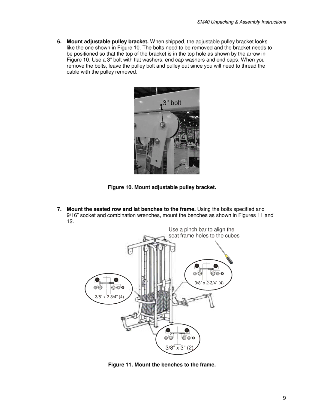
6.Mount adjustable pulley bracket. When shipped, the adjustable pulley bracket looks like the one shown in Figure 10. The bolts need to be removed and the bracket needs to be positioned so that the top of the bracket is in the top hole as shown by the arrow in Figure 10. Use a 3” bolt with flat washers, end cap washers and end caps. When you remove the bolts, leave the pulley bolt and pulley out since you will need to thread the cable with the pulley removed.
Figure 10. Mount adjustable pulley bracket.
7.Mount the seated row and lat benches to the frame. Using the bolts specified and 9/16” socket and combination wrenches, mount the benches as shown in Figures 11 and 12.
Use a pinch bar to align the seat frame holes to the cubes
3/8” x
3/8” x
3/8” x
Figure 11. Mount the benches to the frame.
9