SM50 Unpacking & Assembly Instructions
4.Mount the 56” lat top (part T from HARDWARE section) to the 4-stack cell using a 5/8” socket and combination wrench. Insert two of the large 7/16” by 6” bolts using the hardware configuration shown in Figure 7. Mount the 29” tricep top (part U in HARDWARE section) to the frame and connecting beam (See Figure 7). You will need to remove the pulleys from the teardrop pulley assemblies to gain clearance for the socket wrench extension. Leave the pulleys out of the housings until the cables have been installed.
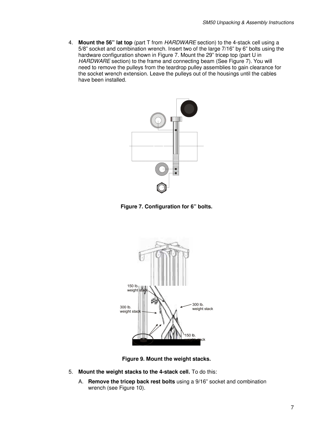
Figure 7. Configuration for 6” bolts.
Figure 9. Mount the weight stacks.
5.Mount the weight stacks to the 4-stack cell. To do this:
A.Remove the tricep back rest bolts using a 9/16” socket and combination wrench (see Figure 10).