Signature Smith Machine
Assembly Instructions
6.Loosen the four set screws on the
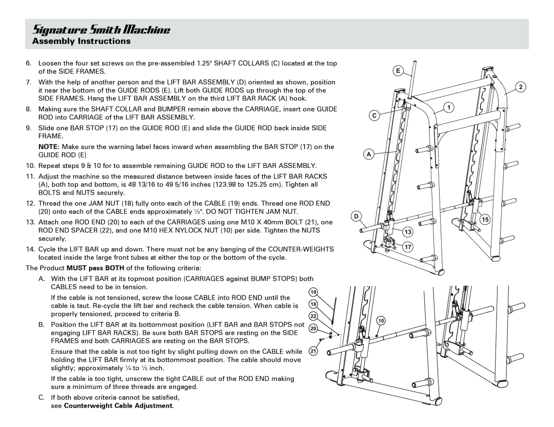
7.With the help of another person and the LIFT BAR ASSEMBLY (D) oriented as shown, position it near the bottom of the GUIDE RODS (E). Lift both GUIDE RODS up through the top of the SIDE FRAMES. Hang the LIFT BAR ASSEMBLY on the third LIFT BAR RACK (A) hook.
8.Making sure the SHAFT COLLAR and BUMPER remain above the CARRIAGE, insert one GUIDE ROD into CARRIAGE of the LIFT BAR ASSEMBLY.
9.Slide one BAR STOP (17) on the GUIDE ROD (E) and slide the GUIDE ROD back inside SIDE FRAME.
NOTE: Make sure the warning label faces inward when assembling the BAR STOP (17) on the
GUIDE ROD (E)
10.Repeat steps 9 & 10 for to assemble remaining GUIDE ROD to the LIFT BAR ASSEMBLY.
11.Adjust the machine so the measured distance between inside faces of the LIFT BAR RACKS (A), both top and bottom, is 48 13/16 to 49 5/16 inches (123.98 to 125.25 cm). Tighten all BOLTS and NUTS securely.
12.Thread the one JAM NUT (18) fully onto each of the CABLE (19) ends. Thread one ROD END (20) onto each of the CABLE ends approximately ½". DO NOT TIGHTEN JAM NUT.
13.Attach one ROD END (20) to each of the CARRIAGES using one M10 X 40mm BOLT (21), one ROD END SPACER (22), and one M10 HEX NYLOCK NUT (10) per side. Tighten the NUTS securely.
14.Cycle the LIFT BAR up and down. There must not be any banging of the
The Product MUST pass BOTH of the following criteria:
A.With the LIFT BAR at its topmost position (CARRIAGES against BUMP STOPS) both CABLES need to be in tension.
If the cable is not tensioned, screw the loose CABLE into ROD END until the | 19 |
| |
cable is taut. | 18 |
| |
properly tensioned, proceed to criteria B. | 22 |
B. Position the LIFT BAR at its bottommost position (LIFT BAR and BAR STOPS not | 20 |
engaging LIFT BAR RACKS). Be sure both BAR STOPS are resting on the SIDE |
|
FRAMES and both CARRIAGES are resting on the BAR STOPS. |
|
Ensure that the cable is not too tight by slight pulling down on the CABLE while | 21 |
holding the LIFT BAR firmly at its bottommost position. The cable should move |
|
slightly; approximately ¼ to ½ inch. |
|
If the cable is too tight, unscrew the tight CABLE out of the ROD END making sure a minimum of three threads are engaged.
C. If both above criteria cannot be satisfied, see Counterweight Cable Adjustment.
E
2
1
C
A
D
15
13
17
10