READ AND UNDERSTAND ALL TRACK, CONNECTOR,
INSTRUCTION SHEETS BEFORE INSTALLING ANY TRACK ITEM
This fixture is intended for installation in accordance with the National Electrical Code and local or Federal regulations. To assure full compliance with codes and regulations, check with your local electrical inspector before installation. To prevent electrical shock, turn off electricity at fuse box before proceeding.
Retain these instructions for maintenance reference.
INSTRUCTION SHEET NO.
IS:26096
0597 | Page 3 of 3 |
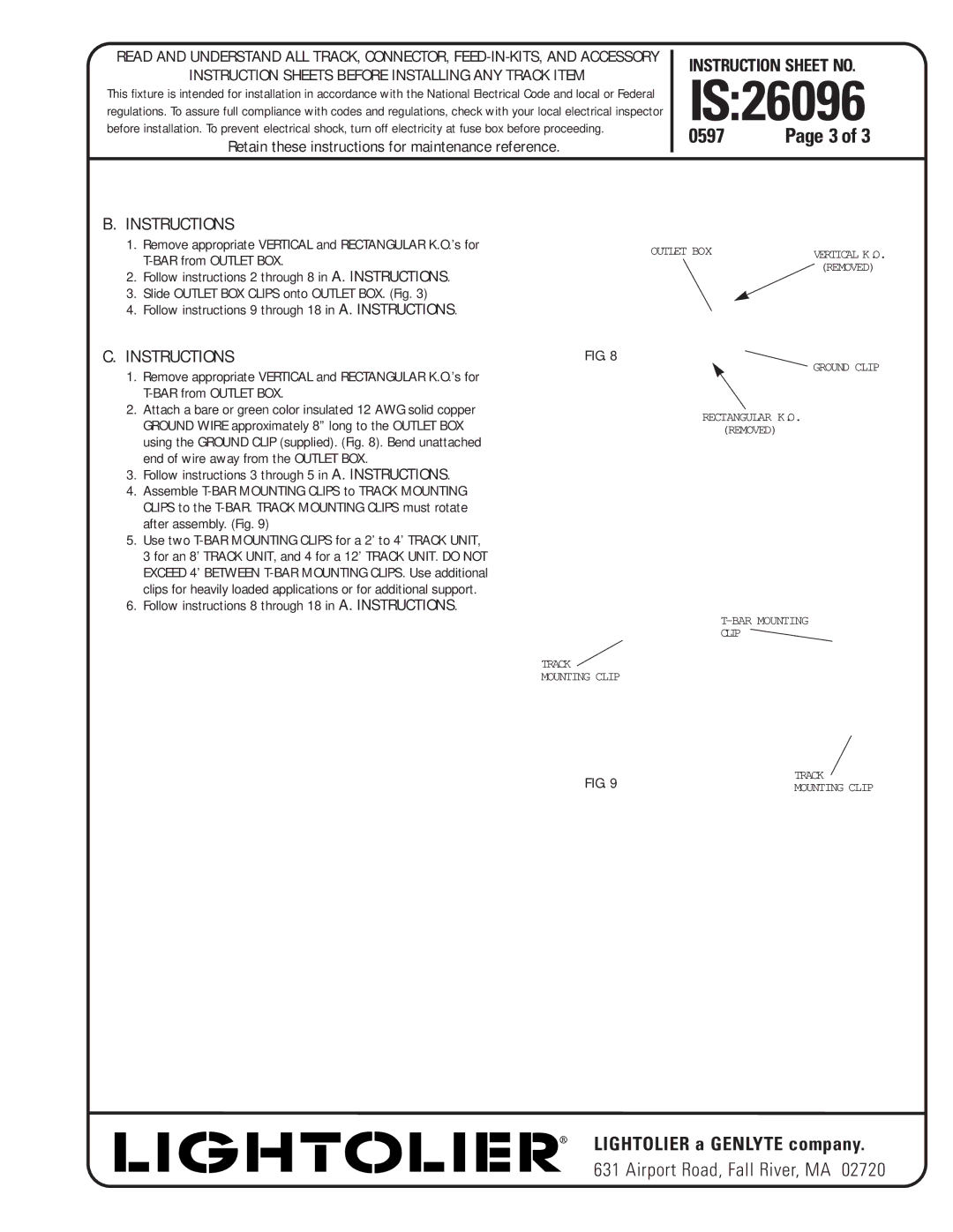
B. INSTRUCTIONS
1. | Remove appropriate VERTICAL and RECTANGULAR K.O.’s for | OUTLET BOX | VERTICAL K.O. |
|
| ||
|
| ||
|
| (REMOVED) | |
2. | Follow instructions 2 through 8 in A. INSTRUCTIONS. |
| |
|
| ||
3. | Slide OUTLET BOX CLIPS onto OUTLET BOX. (Fig. 3) |
|
|
4. | Follow instructions 9 through 18 in A. INSTRUCTIONS. |
|
|
C. INSTRUCTIONS | FIG. 8 | |
1. | Remove appropriate VERTICAL and RECTANGULAR K.O.’s for | GROUND CLIP |
| ||
|
| |
2. | Attach a bare or green color insulated 12 AWG solid copper | RECTANGULAR K.O. |
| GROUND WIRE approximately 8” long to the OUTLET BOX | |
| (REMOVED) | |
using the GROUND CLIP (supplied). (Fig. 8). Bend unattached end of wire away from the OUTLET BOX.
3.Follow instructions 3 through 5 in A. INSTRUCTIONS.
4.Assemble
5.Use two
6.Follow instructions 8 through 18 in A. INSTRUCTIONS.
CLIP
TRACK
MOUNTING CLIP
FIG. 9 | TRACK |
MOUNTING CLIP |
® |