READ AND UNDERSTAND THESE INSTRUCTIONS BEFORE INSTALLING FIXTURE
This fixture is intended for installation in accordance with the National Electrical Code and local regulations. To assure full compliance with local codes and regulations, check with your local electrical inspector before installation. To prevent electrical shock, turn off electricity at fuse box before proceeding.
Retain these instructions for maintenance reference.
INSTRUCTION SHEET NO.
IS:46531
0198 | Page 1 of 3 |
INSTALLATION OF ALICE BATH LIGHTING SERIES
UNPACKING FIXTURE:
•Carefully unpack FIXTURE HOUSING, DIFFUSER DOOR and PARTS BAG from carton.
•Gently remove protective plastic film from outside of FIXTURE HOUSING and any protective paper or plastic film from DIFFUSER DOOR and discard.
FIXTURE INSTALLATION:
The Alice Bath Series can be installed in a variety of ways:
•Directly to standard electrical outlet boxes.
•End to end (continuous runs), using Linear Adapter Kit provided with fixture.
•Using Wall Wiring Mounting Kit (Lightolier Cat. No. 46700) for outlet boxes installed above existing mirrors.
WARNING: (RISK OF FIRE) FOR SUPPLY CONNECTIONS USE WIRE RATED MINIMUM 90°C. MOST DWELLINGS BUILT BEFORE 1985 HAVE SUPPLY WIRE RATED 60°C. CONSULT A QUALIFIED ELECTRICIAN BEFORE INSTALLATION.
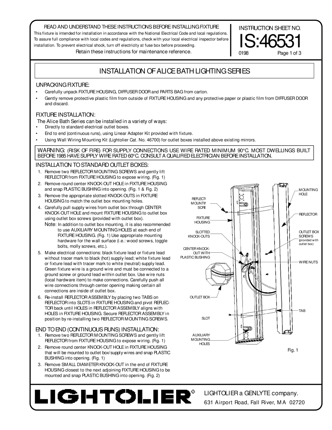
INSTALLATION TO STANDARD OUTLET BOXES:
1.Remove two REFLECTOR MOUNTING SCREWS and gently lift REFLECTOR from FIXTURE HOUSING to expose wiring. (Fig. 1)
2.Remove round center
3.Remove the appropriate slotted
4.Carefully pull supply wires from outlet box through CENTER
Note: In addition to outlet box mounting, it is also recommended to use AUXILIARY MOUNTING HOLES at each end of FIXTURE HOUSING. (Fig. 1) Use appropriate mounting hardware for the wall surface (i.e.: wood screws, toggle bolts, molly screws, etc.).
5.Make electrical connections: black fixture lead or fixture lead without tracer mark to black (hot) supply lead; white fixture lead or fixture lead with tracer mark to white (neutral) supply lead. Green fixture wire is a ground wire and must be connected to a ground screw or ground lead within outlet box. Use wire nuts (local hardware item) to make connections. Carefully push all wire connections through center opening making certain all connections are inside of outlet box.
6.
END TO END (CONTINUOUS RUNS) INSTALLATION:
1.Remove two REFLECTOR MOUNTING SCREWS and gently lift REFLECTOR from FIXTURE HOUSING to expose wiring. (Fig. 1)
2.Remove round center
3.Remove SMALL DIAMETER
|
|
|
|
|
|
| MOUNTING |
REFLECTOR |
|
|
|
|
|
| HOLE |
|
|
|
|
|
|
| |
MOUNTING |
|
|
|
|
|
|
|
|
|
|
|
|
|
| |
SCREW |
|
|
|
|
|
|
|
FIXTURE |
|
|
|
|
|
| REFLECTOR |
|
|
|
|
|
| ||
|
|
|
|
|
|
| |
HOUSING |
|
|
|
|
|
| OUTLET BOX |
SLOTTED |
|
|
|
|
|
| |
|
|
|
|
|
| SCREWS | |
|
|
|
|
|
|
| (provided with |
CENTER KNOCK- |
|
|
|
|
|
| outlet box) |
|
|
|
|
|
|
| |
OUT WITH |
|
|
|
|
|
|
|
|
|
|
|
|
|
| |
PLASTIC BUSHING |
|
|
|
|
|
| WIRE NUTS |
|
|
|
|
|
|
| |
|
|
|
|
|
|
|
OUTLET BOX ![]()
TAB
SLOT
AUXILIARY
MOUNTING
HOLES
Fig. 1