A CLOSER LOOK
PERFORMANCE
Waveform Control Technology®
CV/CCAC
Driving Superior Welding Performance
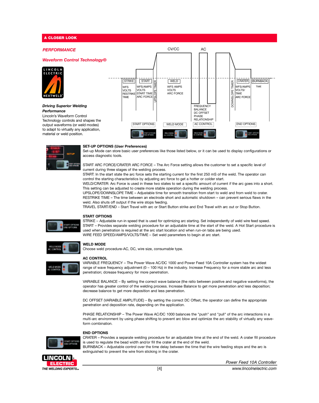
Lincoln’s Waveform Control Technology controls and shapes the output waveforms (or weld modes) to adapt to virtually any application, material or weld position.
|
|
|
|
|
|
STRIKE |
|
| START |
| TIMER |
|
|
|
|
| |
WFS | WFS/AMPS | ||||
VOLTS | VOLTS | UPSLOPE | |||
RESTRIKE | START TIME | ||||
TIME | ARC FORCE |
| |||
|
|
|
|
|
|
![]() START OPTIONS
START OPTIONS ![]()
WELD
WFS AMPS
VOLTS
ARC FORCE
FREQUENCY
BALANCE
DC OFFSET
PHASE
RELATIONSHIP
WELD MODE | AC CONTROL |
DOWNSLOPE TIMER
CRATER ![]()
![]() BURNBACK
BURNBACK
WFS/AMPS | TIME |
VOLTS/ |
|
TIME |
|
ARC FORCE |
|
![]() END OPTIONS
END OPTIONS ![]()
SETUP
SET-UP OPTIONS (User Preferences)
START ARC FORCE/CRATER ARC FORCE – The Arc Force setting allows the customer to set a specific level of current during three stages of the welding process.
START: In the start state the arc force sets the starting current for the first 250 mS of the weld. The operator can control the starting characteristics by adjusting arc force to get a hotter or colder start.
WELD/CRATER: Arc Force is used in these two states to set a specific amount of current if the arc goes into a short. This setting can be adjusted to create more stable operation during the welding process.
UPSLOPE/DOWNSLOPE TIME – Adjustable time for smooth transition from start to weld and from weld to crater. RESTRIKE TIME – The time between an electrode short and automatic shutdown – can prevent serious flaws in the weld. Also shuts off output if the wire stops feeding.
TRAVEL START/END – Start Travel with arc or Start Button strike and End Travel with arc out or Stop Button.
START OPTIONS
STRIKE – Adjustable
WIRE FEED SPEED/AMPS/VOLTS/TIME – Set weld parameters to begin at arc start.
WELD MODE
Choose weld
AC CONTROL
VARIABLE FREQUENCY – The Power Wave AC/DC 1000 and Power Feed 10A Controller system has the widest range of wave frequency adjustment (0 – 100 Hz) in the industry. Increase Frequency for a more stable arc and less penetration; dcrease frequency for more penetration.
VARIABLE BALANCE – By setting the correct wave balance (the ratio between positive and negative waveforms), the operator has greater control of the welding process. Increase Balance to get more penetration and less deposition; decrease balance to get more deposition and less penetration.
DC OFFSET (VARIABLE AMPLITUDE) – By setting the correct DC Offset, the operator can define the appropriate penetration and deposition rate, depending on the application.
PHASE RELATIONSHIP – The Power Wave AC/DC 1000 balances the "push" and "pull" of the arc interactions in a
END OPTIONS
CRATER – Provides a separate welding procedure for an adjustable time at the end of the weld. A crater fill procedure is used to regulate the bead width and/or fill the crater at the end of the weld.
BURNBACK – Adjustable control over the time delay between the time that the wire feeding stops and the arc is extinguished to prevent the wire from sticking in the crater.
| Power Feed 10A Controller |
[4] | www.lincolnelectric.com |
