B-3

OPERATION

B-3


CONTROLS AND SETTINGS

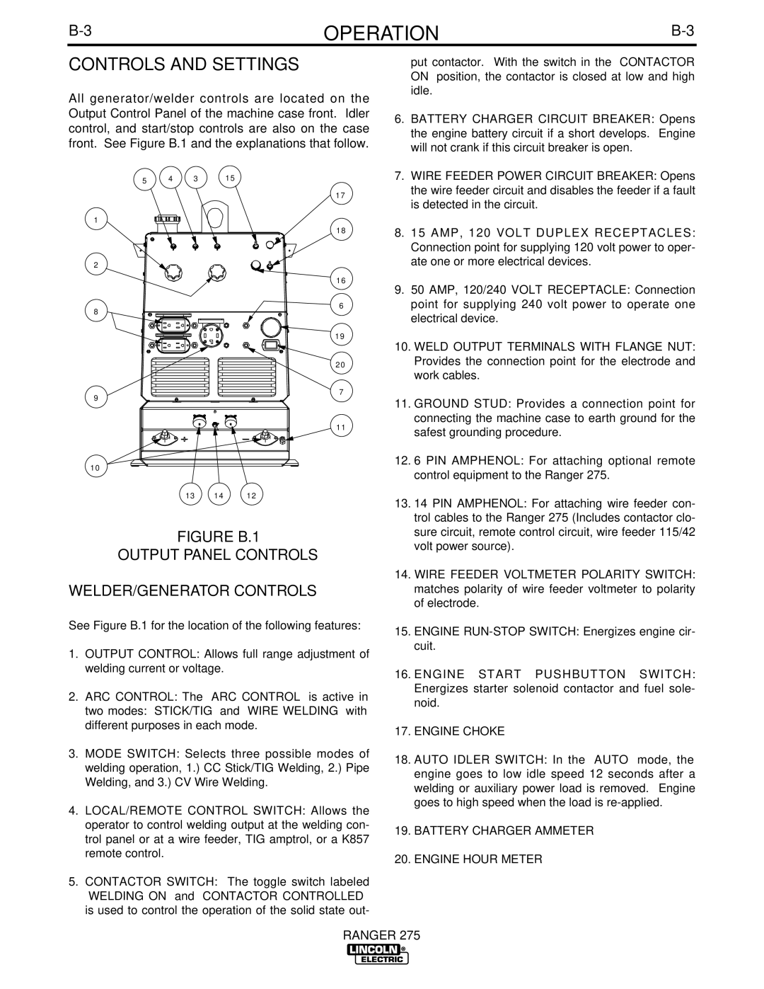
All generator/welder controls are located on the Output Control Panel of the machine case front. Idler control, and start/stop controls are also on the case front. See Figure B.1 and the explanations that follow.

put contactor. With the switch in the “CONTACTOR ON” position, the contactor is closed at low and high idle.

6. BATTERY CHARGER CIRCUIT BREAKER: Opens

the engine battery circuit if a short develops. Engine

will not crank if this circuit breaker is open.

5 4 3

1

2

8

9

15

17

18

16

6

19

20

7

7.

WIRE FEEDER POWER CIRCUIT BREAKER: Opens


the wire feeder circuit and disables the feeder if a fault


is detected in the circuit.

8.

15 AMP, 120 VOLT DUPLEX RECEPTACLES:


Connection point for supplying 120 volt power to oper-


ate one or more electrical devices.

9.

50 AMP, 120/240 VOLT RECEPTACLE: Connection


point for supplying 240 volt power to operate one


electrical device.

10. WELD OUTPUT TERMINALS WITH FLANGE NUT:


Provides the connection point for the electrode and


work cables.

11. GROUND STUD: Provides a connection point for


connecting the machine case to earth ground for the

11

10

13 14 12

FIGURE B.1

OUTPUT PANEL CONTROLS

WELDER/GENERATOR CONTROLS

See Figure B.1 for the location of the following features:

1.OUTPUT CONTROL: Allows full range adjustment of welding current or voltage.

2.ARC CONTROL: The “ARC CONTROL” is active in

two modes: “STICK/TIG” and “WIRE WELDING” with different purposes in each mode.

3.MODE SWITCH: Selects three possible modes of welding operation, 1.) CC Stick/TIG Welding, 2.) Pipe Welding, and 3.) CV Wire Welding.

4.LOCAL/REMOTE CONTROL SWITCH: Allows the operator to control welding output at the welding con- trol panel or at a wire feeder, TIG amptrol, or a K857 remote control.

5.CONTACTOR SWITCH: The toggle switch labeled “WELDING ON” and “CONTACTOR CONTROLLED” is used to control the operation of the solid state out-

safest grounding procedure.

12. 6 PIN AMPHENOL: For attaching optional remote

control equipment to the Ranger 275.

13. 14 PIN AMPHENOL: For attaching wire feeder con-

trol cables to the Ranger 275 (Includes contactor clo-

sure circuit, remote control circuit, wire feeder 115/42

volt power source).

14. WIRE FEEDER VOLTMETER POLARITY SWITCH:

matches polarity of wire feeder voltmeter to polarity

of electrode.

15. ENGINE RUN-STOP SWITCH: Energizes engine cir-

cuit.

16. ENGINE START PUSHBUTTON SWITCH:

Energizes starter solenoid contactor and fuel sole-

noid.

17. ENGINE CHOKE

18. AUTO IDLER SWITCH: In the “AUTO” mode, the

engine goes to low idle speed 12 seconds after a

welding or auxiliary power load is removed. Engine

goes to high speed when the load is re-applied.

19. BATTERY CHARGER AMMETER

20. ENGINE HOUR METER

RANGER 275

Page 19
Image 19
Lincoln Electric 275 manual Controls and Settings, Figure B.1 Output Panel Controls WELDER/GENERATOR Controls

275 specifications

The Lincoln Electric 275 is a versatile multi-process welding machine that stands out for its advanced features and robust performance. Designed for both novice and experienced welders, the machine offers MIG, TIG, and stick welding capabilities, making it a valuable tool for a variety of applications.

One of the main features of the Lincoln Electric 275 is its power output. With an impressive selection of amperage settings, it can deliver between 25 to 275 amps, making it suitable for both thin and thick materials. This flexibility allows users to work on projects ranging from automotive repairs to industrial fabrication.

The machine utilizes inverter technology, which significantly enhances its efficiency and reduces power consumption. Inverter welders are known for their lightweight design and compact size compared to traditional transformer-based welders. This portability makes the Lincoln Electric 275 easy to transport to job sites, catering to both professional and hobbyist welders who require mobility.

Another defining characteristic of the Lincoln Electric 275 is its easy-to-use interface. The digital display provides clear readings, allowing users to effortlessly adjust settings for optimal performance. Additionally, the machine features a user-friendly control panel with distinct knobs for regulating voltage and wire feed speed, assisting welders in achieving precise welds.

The Lincoln Electric 275 is also equipped with advanced arc technologies. Its built-in arc control enhances the stability of the welding arc, resulting in a smoother, more consistent weld. Furthermore, the machine offers synergic controls that automatically adjust the voltage and wire feed speed based on the selected material and thickness, making the welding process more intuitive and reducing the margin for error.

Durability is another hallmark of the Lincoln Electric 275. Constructed with high-quality materials, the machine is built to withstand the rigors of daily use in demanding environments. Its design also incorporates efficient cooling mechanisms to prevent overheating during prolonged operations, ensuring longevity and reliability.

In conclusion, the Lincoln Electric 275 is a powerful and adaptable welding machine that combines advanced technology with user-friendly features. Its multi-process capabilities, inverter technology, and robust construction make it an essential tool for both professional welders and DIY enthusiasts. Whether tackling intricate projects or heavy-duty tasks, the Lincoln Electric 275 proves to be a reliable choice that does not compromise on performance.