275 specifications
The Lincoln Electric 275 is a versatile multi-process welding machine that stands out for its advanced features and robust performance. Designed for both novice and experienced welders, the machine offers MIG, TIG, and stick welding capabilities, making it a valuable tool for a variety of applications.One of the main features of the Lincoln Electric 275 is its power output. With an impressive selection of amperage settings, it can deliver between 25 to 275 amps, making it suitable for both thin and thick materials. This flexibility allows users to work on projects ranging from automotive repairs to industrial fabrication.
The machine utilizes inverter technology, which significantly enhances its efficiency and reduces power consumption. Inverter welders are known for their lightweight design and compact size compared to traditional transformer-based welders. This portability makes the Lincoln Electric 275 easy to transport to job sites, catering to both professional and hobbyist welders who require mobility.
Another defining characteristic of the Lincoln Electric 275 is its easy-to-use interface. The digital display provides clear readings, allowing users to effortlessly adjust settings for optimal performance. Additionally, the machine features a user-friendly control panel with distinct knobs for regulating voltage and wire feed speed, assisting welders in achieving precise welds.
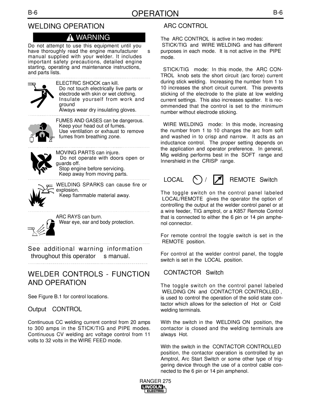
The Lincoln Electric 275 is also equipped with advanced arc technologies. Its built-in arc control enhances the stability of the welding arc, resulting in a smoother, more consistent weld. Furthermore, the machine offers synergic controls that automatically adjust the voltage and wire feed speed based on the selected material and thickness, making the welding process more intuitive and reducing the margin for error.
Durability is another hallmark of the Lincoln Electric 275. Constructed with high-quality materials, the machine is built to withstand the rigors of daily use in demanding environments. Its design also incorporates efficient cooling mechanisms to prevent overheating during prolonged operations, ensuring longevity and reliability.
In conclusion, the Lincoln Electric 275 is a powerful and adaptable welding machine that combines advanced technology with user-friendly features. Its multi-process capabilities, inverter technology, and robust construction make it an essential tool for both professional welders and DIY enthusiasts. Whether tackling intricate projects or heavy-duty tasks, the Lincoln Electric 275 proves to be a reliable choice that does not compromise on performance.

