OPERATION | ||
|
|
|
![]() CAUTION
CAUTION
Operating the starter motor for more than 5 sec- onds can damage the motor. If the engine fails to start, release the switch and wait 10 seconds before operation the starter again. Do NOT push the START button while the engine is running because this can damage the ring gear and/or the starter motor.
NOTE: When starting a RANGER 305G for the first time, or after and extended period of time of not operat- ing, it will take longer than normal because the fuel pump has to fill the fuel line and carburetor.
STOPPING
Remove all welding and auxiliary power loads and allow the engine to run at low idle speed for a few min- utes to cool the engine.
Stop the engine by placing the
NOTE: A fuel shut off valve is not required on the RANGER 305G because the fuel tank is mounted below the engine.
WELDER OPERATION
DUTY CYCLE
Duty Cycle is the percentage of time the load is being applied in a 10 minute period. For Example, a 60% duty cycle represents 6 minutes of load and 4 minutes of no load in a 10 minute period.
DC STICK WELDING
The RANGER 305G can be used with a broad range of DC stick electrodes.
The MODE switch provides two stick welding settings as follows:
CONSTANT CURRENT (CC-STICK) WELDING
The
The ARC CONTROL knob sets the short circuit current during stick welding
DOWN HILL PIPE WELDING
This slope controlled setting is intended for
The ARC CONTROL knob sets the short circuit current during stick welding
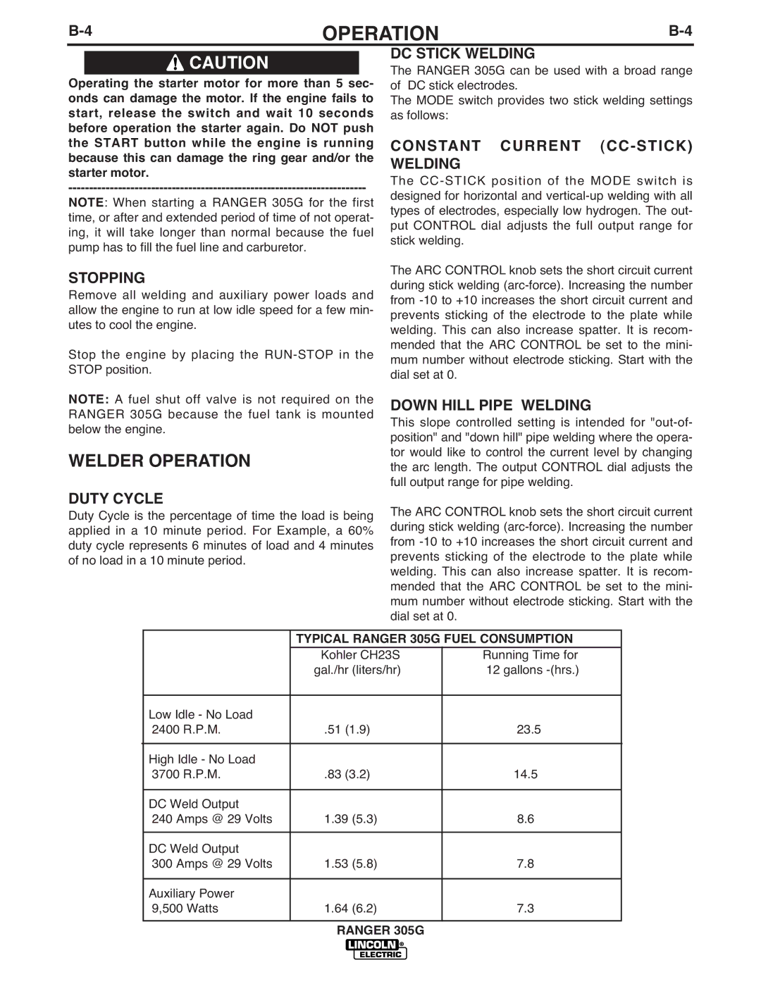
| TYPICAL RANGER 305G FUEL CONSUMPTION | |
| Kohler CH23S | Running Time for |
| gal./hr (liters/hr) | 12 gallons |
|
|
|
Low Idle - No Load |
|
|
2400 R.P.M. | .51 (1.9) | 23.5 |
|
|
|
High Idle - No Load |
|
|
3700 R.P.M. | .83 (3.2) | 14.5 |
|
|
|
DC Weld Output |
|
|
240 Amps @ 29 Volts | 1.39 (5.3) | 8.6 |
|
|
|
DC Weld Output |
|
|
300 Amps @ 29 Volts | 1.53 (5.8) | 7.8 |
|
|
|
Auxiliary Power |
|
|
9,500 Watts | 1.64 (6.2) | 7.3 |
|
|
|
RANGER 305G