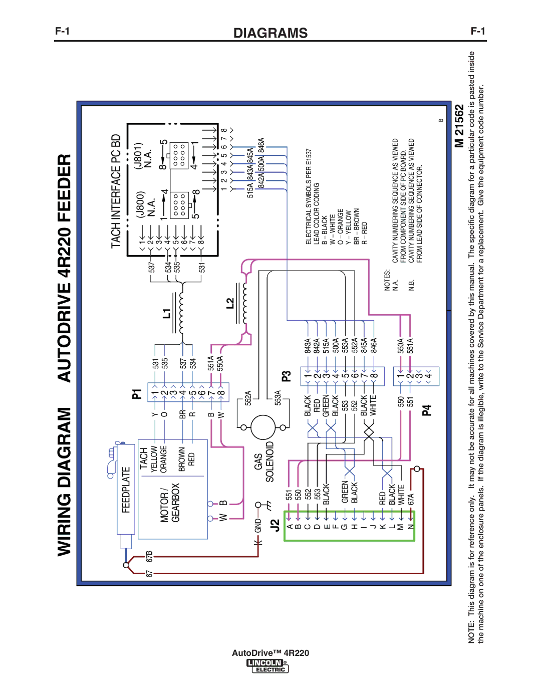
WIRING DIAGRAM AUTODRIVE 4R220 FEEDER
![]() AutoDrive™ 4R220
AutoDrive™ 4R220
67 67B
FEEDPLATE |
|
|
|
|
| TACH INTERFACE PC BD |
| |||||||
| P1 |
|
|
|
|
|
|
|
|
|
|
| ||
| TACH |
|
|
|
| 1 | (J800) |
|
| (J801) |
| |||
|
|
|
|
|
| N.A. |
|
|
| N.A. |
|
| ||
| YELLOW | Y | 1 | 531 |
| 537 | 2 |
|
|
|
|
| ||
MOTOR / |
|
| 3 | 1 |
|
|
| 8 | 5 |
| ||||
ORANGE | O | 2 | 535 | L1 |
| 4 |
|
|
| |||||
534 | 4 |
|
|
| ||||||||||
GEARBOX |
|
| 3 |
|
| 535 | 5 |
|
|
|
|
|
|
|
| BROWN | BR | 4 | 537 |
|
| 6 |
|
|
|
|
|
|
|
| RED | R | 5 | 534 |
|
| 7 | 5 | 8 |
|
| 4 | 1 |
|
|
|
| 6 |
|
| 531 | 8 |
|
|
|
|
|
|
|
|
| B | 7 | 551A |
|
|
|
|
|
|
|
|
|
|
W B |
| W | 8 | 550A | L2 |
|
|
| 1 | 2 | 3 | 4 5 | 6 7 | 8 |
|
|
|
|
|
|
|
|
|
|
|
|
|
| |
552A | 515A 843A 845A |
GND | GAS |
|
|
|
| 842A 500A 846A | |
J2 | SOLENOID | 553A |
|
|
|
| |
| P3 |
|
|
| |||
A | 551 |
|
|
|
| ||
B | 550 |
| 1 |
|
|
| |
C | 552 | BLACK | 843A |
| ELECTRICAL SYMBOLS PER E1537 | ||
D | 553 | RED | 2 | 842A |
| LEAD COLOR CODING | |
E | BLACK | GREEN | 3 | 515A |
| B – BLACK | |
F |
| BLACK | 4 | 500A |
| W – WHITE | |
|
| O – ORANGE | |||||
G | GREEN | 553 | 5 | 553A |
| ||
| Y – YELLOW | ||||||
H | BLACK | 552 | 6 | 552A |
| BR – BROWN | |
I |
| BLACK | 7 | 845A |
| R – RED | |
J | RED | WHITE | 8 | 846A |
|
| |
K |
|
|
| NOTES: |
| ||
L | BLACK |
|
|
|
| ||
| 1 | 550A | N.A. | CAVITY NUMBERING SEQUENCE AS VIEWED | |||
M | WHITE | 550 | |||||
| FROM COMPONENT SIDE OF PC BOARD. | ||||||
N | 67A | 551 | 2 | 551A | N.B. | CAVITY NUMBERING SEQUENCE AS VIEWED | |
|
| P4 | 3 |
|
| FROM LEAD SIDE OF CONNECTOR. | |
|
| 4 |
|
|
|
B
DIAGRAMS
M 21562
NOTE: This diagram is for reference only. It may not be accurate for all machines covered by this manual. The specific diagram for a particular code is pasted inside the machine on one of the enclosure panels. If the diagram is illegible, write to the Service Department for a replacement. Give the equipment code number.
