OPERATION | ||
|
|
|
(See Customer Assistance Policy in the front of this Instruction Manual)
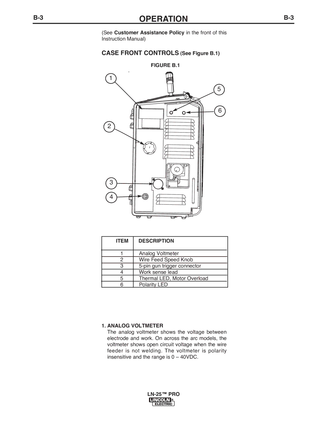
CASE FRONT CONTROLS (See Figure b.1)
FIGURE b.1
1
5
6
2
3
4
ITEM | DESCRIPTION | |
|
|
|
1 | Analog Voltmeter | |
2 | Wire Feed Speed Knob | |
3 | ||
4 | Work sense lead | |
5 | Thermal LED, Motor Overload |
|
6 | Polarity LED | |
1.ANALOG VOLTMETER
The analog voltmeter shows the voltage between electrode and work. On across the arc models, the voltmeter shows open circuit voltage when the wire feeder is not welding. The voltmeter is polarity insensitive and the range is 0 – 40VDC.