INSTALLATION | ||
|
|
|
POWER SOURCE TO LN-25™ PRO
CAbLE CONNECTION DIAGRAMS
ACROSS THE ARC SET-UPS
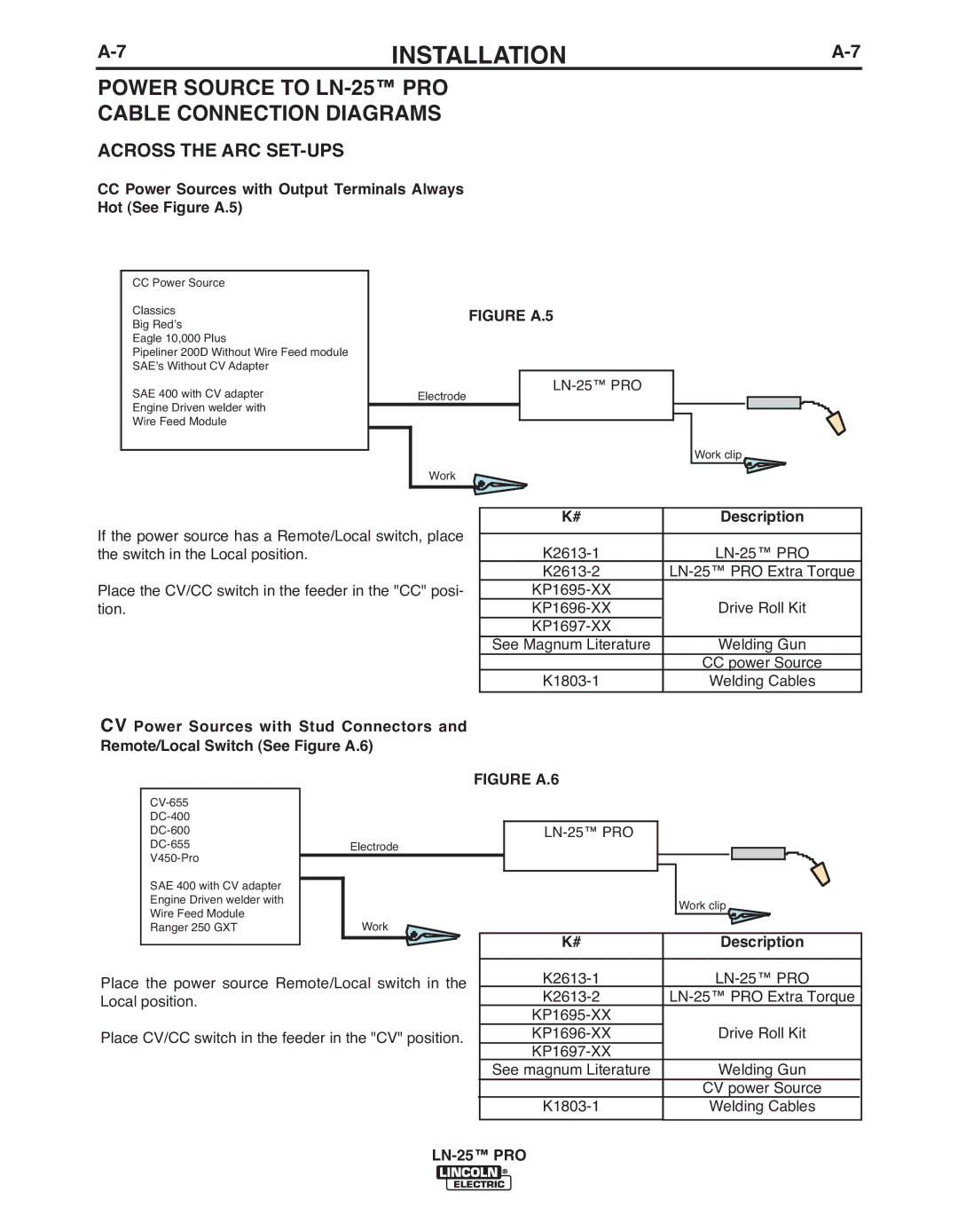
CCPower Sources with Output Terminals Always Hot (See Figure A.5)
CC Power Source |
|
|
| |
Classics |
|
|
| |
| FIGURE A.5 |
| ||
Big Red’s |
|
| ||
|
|
| ||
Eagle 10,000 Plus |
|
|
| |
Pipeliner 200D Without Wire Feed module |
|
|
| |
SAE’s Without CV Adapter |
| |||
SAE 400 with CV adapter | Electrode | |||
|
| |||
Engine Driven welder with |
|
|
| |
Wire Feed Module |
|
|
| |
|
|
| Work clip | |
| Work |
|
| |
If the power source has a Remote/Local switch, place the switch in the Local position.
Place the CV/CC switch in the feeder in the "CC" posi- tion.
CV Power Sources with Stud Connectors and Remote/Local Switch (See Figure A.6)
| |
| |
| |
Electrode | |
| |
SAE 400 with CV adapter |
|
Engine Driven welder with |
|
Wire Feed Module | Work |
Ranger 250 GXT |
Place the power source Remote/Local switch in the Local position.
Place CV/CC switch in the feeder in the "CV" position.
| K# | Description | |
|
|
| |
| |||
| |||
|
| ||
| Drive Roll Kit | ||
|
| ||
| See Magnum Literature | Welding Gun | |
|
|
| CC power Source |
| Welding Cables | ||
|
|
|
|
|
|
|
|
FIGURE A.6 |
| ||
|
|
|
|
|
| ||
|
|
| Work clip |
|
|
| |
| K# | Description | |
|
|
| |
| |||
| |||
|
| ||
| Drive Roll Kit | ||
|
| ||
| See magnum Literature | Welding Gun | |
|
|
| CV power Source |
| Welding Cables | ||
|
|
|
|