Manuals
/
Lincoln Electric
/
Power Tools
/
Welding System
Lincoln Electric
IM10031-A
manual
Dimension Print
Models:
IM10031-A
1
40
43
43
Download
43 pages
1.67 Kb
36
37
38
39
40
41
42
43
Troubleshooting
Specs
Install
Diagrams
Wire Feeder
Dimension
Wire Drive Configuration
PRObLEMS
Accessories
Pressure ARM Adjustment
Page 40
Image 40
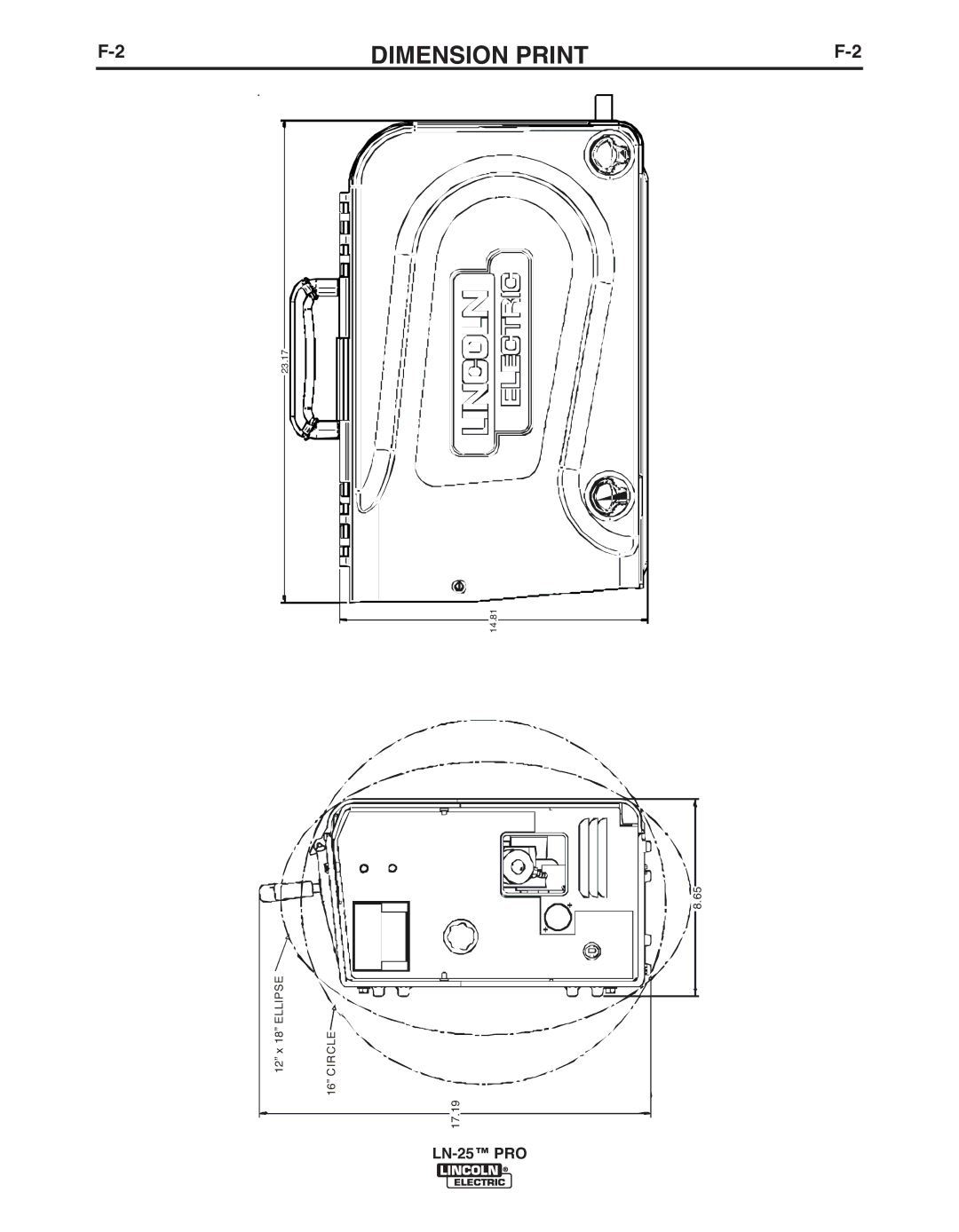
F-2
DIMENSION PRINT
F-2
23.17
14.81
8.65
12” x 18” ELLIPSE
CIRCLE
16”
17.19
LN-25™
PRO
Page 39
Page 41
Page 40
Image 40
Page 39
Page 41
Contents
LN-25 Tmpro
Safety
California Proposition 65 Warnings
Electric Shock can kill
Welding and Cutting Sparks can Cause fire or explosion
Iii
Précautions DE Sûreté
Sûreté Pour Soudage a L’Arc
Electromagnetic Compatibility EMC
Methods of Reducing Emissions Mains Supply
Please Examine Carton and Equipment For Damage Immediately
Vii
On-Line Product Registration
TAbLE of Contents
Installation
Technical Specifications LN-25 PRO K2613-1, K2613-2
Wire SIzES
LN-25 PRO
Safety Precautions
Location
High Frequency Protection
Weld CAbLE SIzE
3INSTALLATIONA-3
Power Source
Wire Feeder
Analog Control CAbLE K1797-xx
CAbLE Connections
Function Pin Wiring
Shielding GAS Connection
Procedure to Install Drive Rolls and Wire Guides
Wire Drive Configuration
Changing the GUN Receiver bUSHING
Pressure ARM Adjustment
Loading Spools of Wire
GUN Connection
Fe, CrNi
Across the ARC SET-UPS
Power Source to LN-25 PRO
Description
Figure A.7
9INSTALLATIONA-9
Figure A.9
Safety Precautions
Operation
General Description
Case Front Controls See Figure b.1
Figure b.1
Wire Feed Speed KNOb
Wire Feed Speed, CV Operation
Minimum Arc Volts Maximum WFS
Extra Torque
Polarity LED
Internal Controls
Figure b.2
Step Trigger Interlock Switch
Internal Controls Description
Cold Feed PUSHbUTTON
Step Trigger
Constant Current Wire Welding
Figure b-3
Itemdescription
Rear Controls
POWER-UP Sequence
GAS Purge PUSHbUTTON
Flow Meter
Liter/Min
Accessories
Factory Installed Equipment
Drive Roll Kits
Electrode SIzE
On at all times
Accessories
K1500-5 Gun Receiver Bushing compatible
Installation of the K590-6 Water Cooling KIT
Maintenance
Routine Maintenance
Periodic Maintenance
CALIbRATION Specification
Wire Feed Speed Validation
To change the wire feed speed calibration See Figure D.2
Model gearing
BOARD LN-25 PRO
TROUbLESHOOTING
Electric Shock can kill
PRObLEMS
Symptoms
POSSIbLE
Cause Recommended Course of Action
TROUbLESHOOTING
Diagrams
Enhanced Diagram
Dimension Print
Precaucion
Warnung
Top
Page
Image
Contents