OPERATION | ||
|
|
|
CONTROLS AND SETTINGS
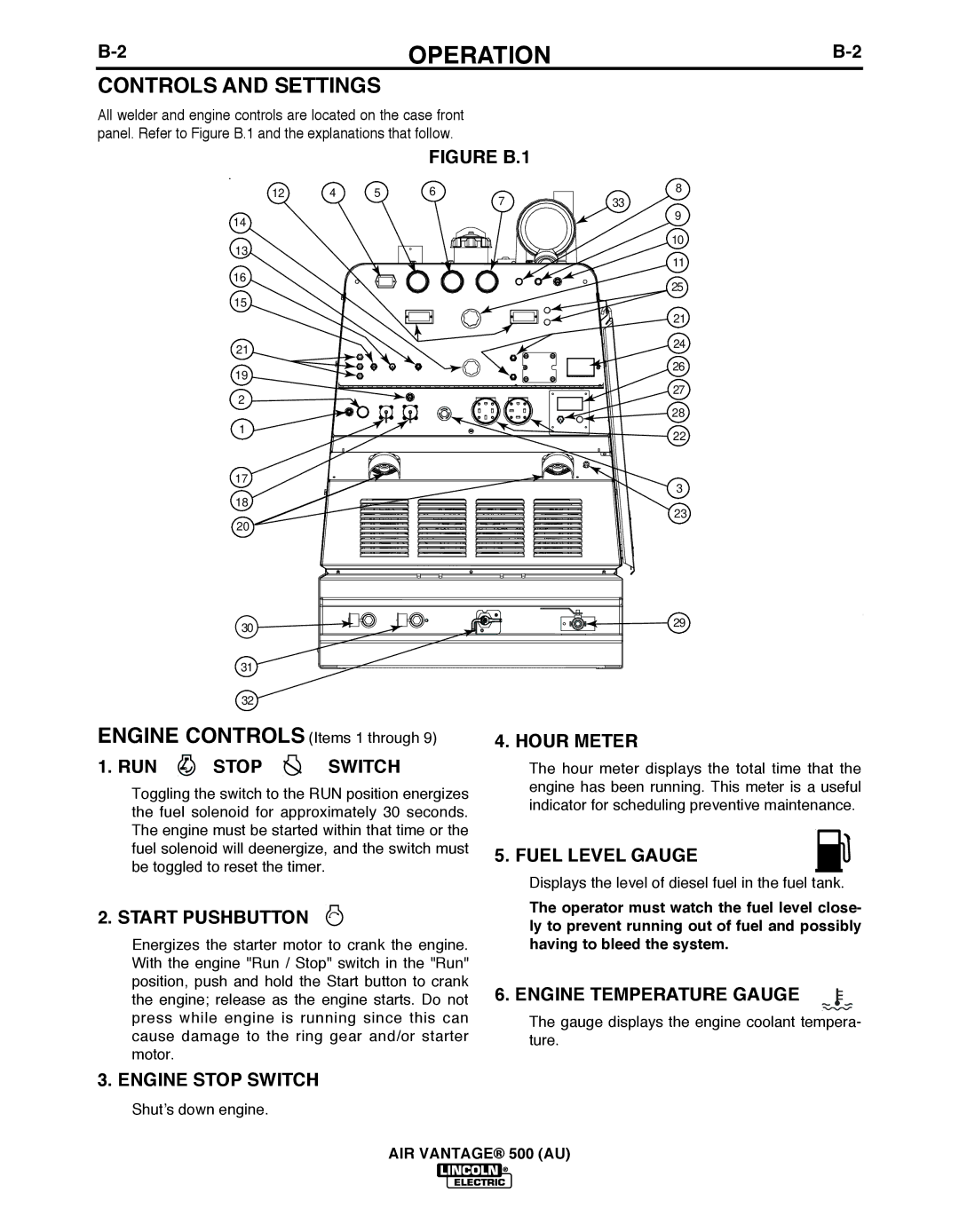
All welder and engine controls are located on the case front panel. Refer to Figure B.1 and the explanations that follow.
FIGURE b.1
12 | 4 | 5 | 6 | 7 |
|
|
|
|
14
33
8
9
13
16
15
21![]()
![]()
![]() 19
19![]()
![]()
![]()
![]()
![]()
![]()
![]()
![]()
![]()
![]()
![]()
![]()
![]()
![]()
![]()
![]()
![]() 2
2 ![]()
![]()
![]()
![]()
![]()
![]()
![]() 1
1 ![]()
![]()
![]()
![]()
![]()
![]()
![]()
![]()
![]()
![]()
![]()
![]()
![]()
![]()
10
11
25
21
24
26
27
28
22
17 | 3 | |
18 | ||
23 | ||
20 | ||
|
30 | 29 |
|
31
32
ENGINE CONTROLS (Items 1 through 9)
1. RUN  STOP
STOP  SWITCH
Toggling the switch to the RUN position energizes the fuel solenoid for approximately 30 seconds. The engine must be started within that time or the fuel solenoid will deenergize, and the switch must be toggled to reset the timer.
2. START PUSHbUTTON
Energizes the starter motor to crank the engine. With the engine "Run / Stop" switch in the "Run" position, push and hold the Start button to crank the engine; release as the engine starts. Do not press while engine is running since this can cause damage to the ring gear and/or starter motor.
4. HOUR METER
The hour meter displays the total time that the engine has been running. This meter is a useful indicator for scheduling preventive maintenance.
5. FUEL LEVEL GAUGE
Displays the level of diesel fuel in the fuel tank.
The operator must watch the fuel level close- ly to prevent running out of fuel and possibly having to bleed the system.
6. ENGINE TEMPERATURE GAUGE
The gauge displays the engine coolant tempera- ture.
3. ENGINE STOP SWITCH
Shut’s down engine.
AIR VANTAGE® 500 (AU)